loCating the unit
IM 930-6 •EnnityVerticalWaterSourceHeatPumps 6 www.DaikinApplied.com
1. Locatetheunitinanareathatallowsforeasy
removalofthelterandaccesspanels,andhas
enoughspaceforservicepersonneltoperform
maintenanceorrepair.Providesufcientroomto
makewater,electricalandductconnections.
2. Makesurethatsufcientaccesshasbeenprovidedfor
installingtheunit,includingclearanceforductcollars
andttingsatwaterandelectricalconnections.
3. Allowadequateroomaroundtheunitfora
condensatepiping.
4. Theunitcanbeinstalled“freestanding”inan
equipmentroom.However,closetinstallationsare
morecommonforsmallverticaltypeunits.
Generally,theunitislocatedinthecornerofacloset
withthenon-ductedreturnairfacing90°tothedoorand
themajoraccesspanelsfacingthedoorasinFigure1.
Alternatively,theunitcanhaveaductedreturnairwith
theopeningfacingthedoorandthemajoraccesspanels
facing90°tothedoorasinFigure2.
5. Unitmustbelocatedontopofavibrationabsorbing
materialsuchasarubber(Isolationpad)thatis
thesamesizeasthebaseoftheunit,tominimize
vibrationandnoise.SeeFigure9onpage10.
Minimum distance requirement from
return air duct collar to wall for non-
ducted units.
Model Distance
009–012 ....................... 5inches
015–024 ....................... 5inches
030–036 ....................... 6inches
042–048 ....................... 8inches
060–070 ..................... 10inches
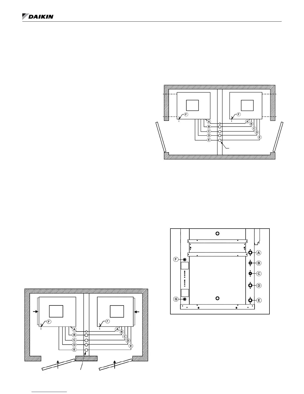
Figure 1: Typical closet installation with louver door return
(non-ducted)
ReturnAirThru
LouveredDoor
ReturnAirThru
LouveredDoor
Return
Air
Risers
Left-HandReturnAir
Arrangement
Right-HandReturnAir
Arrangement
Return
Air
A Condensate
B DesuperheaterWaterReturn(Optional)
C DesuperheaterWaterSupply(Optional)
D WaterReturn
E WaterSupply
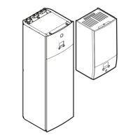
Figure 2: Typical closet installation with ducted return
HeatPumpwith
Right-HandReturnAir
Arrangement
HeatPumpwith
Left-HandReturnAir
Arrangement
Return
Air
Duct&
Grille
Return
Air
Duct&
Grille
Risers
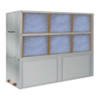
A Condensate
B DesuperheaterWaterReturn(Optional)
C DesuperheaterWaterSupply(Optional)
D WaterReturn
E WaterSupply
F LowVoltageControlWiring(ElectricEntrance)
G LineVoltageUnitPower(ElectricEntrance)
Figure 3: Unit Electrical and Piping Locations
ControlAccessPanel