www.DaikinApplied.com 31 EnnityVerticalWaterSourceHeatPumps• IM 930-6
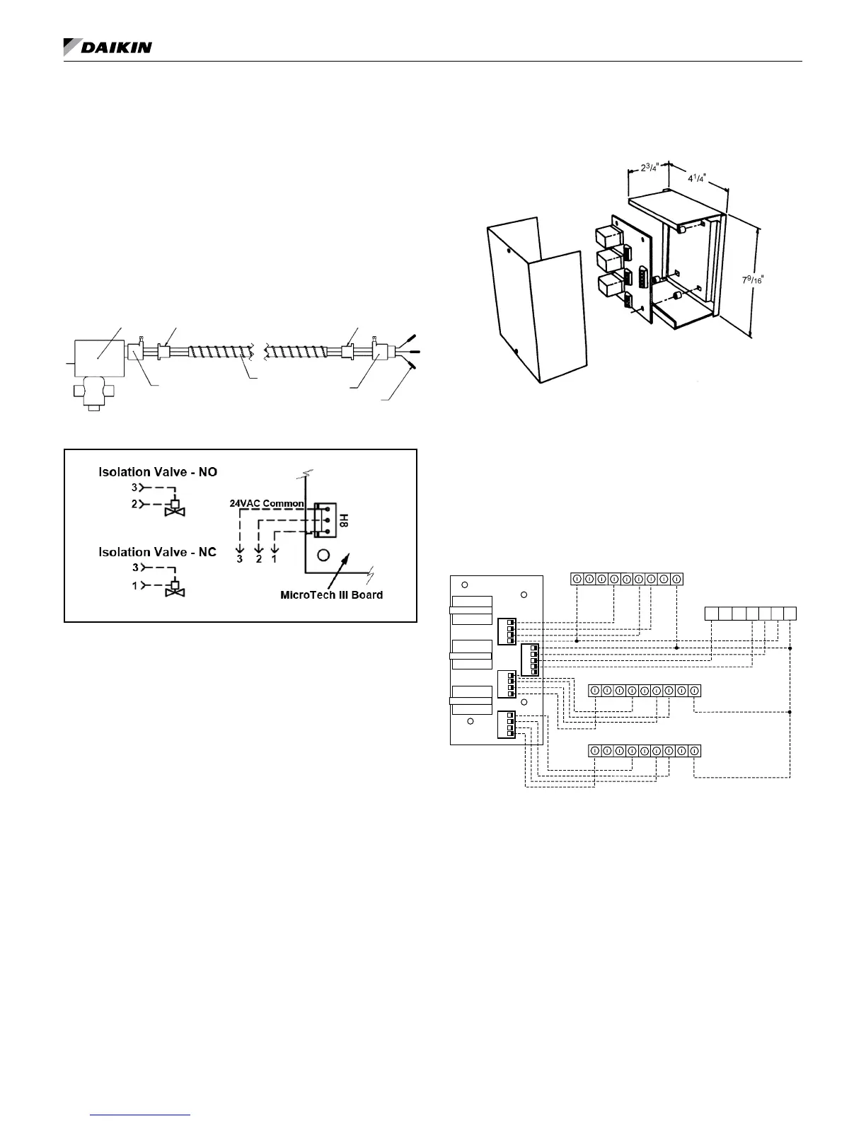
Motorized Isolation Valve & Relay
Themotorizedvalvekitisavailableasafactory-installed
andwiredoptionormaybeorderedasaeld-installed
accessory.
WiredasshowninFigure29,themotorizedvalvewillopen
onacallforcompressoroperation.Valvesforunitsizes
009to019are1/2"whileunitsizes024to070are3/4".
UsingaNormallyClosed(N/C),poweropenvalve,wire
asillustratedinFigure29.
Figure 29: Normally Closed, Power Open Motorized Valve
& Relay Wiring
Actuator&
ValveAssembly
Anti-shortBushing
Connector
Conduit
Pin(s),female
plugintoreceptacle
congurationbelow
Connector
Anti-short
Bushing
Note: Connectors on valve must be cut off and stripped
back and the wires twisted to make connections
to the IV/PR Terminals
Pump Restart Relay Kit P/N 061419001
TheMicroTechIIIunitcontrollerhasaninternalPump
RestartRelayconnectedtoH8,Pin2fortheNormally
Open(N/O)terminaloftheinternalrelay.
ConnecttoH8,Pin1fortheNormallyClosed(N/C)
terminaloftheinternalrelay.
Theoutputoftheinternalpumprestartrelayis24-
voltsACandtheoutputisnotavailablewhentheH8
connectionisusedtocontrolamotorizedvalve.
Multiple Unit Control (up to 3 units)
(P/N 056794201)
Themultipleunitcontrolboardisanaccessoryusedwhen
upto3-unitsarecontrolledfromasinglethermostat.
Typicallythecontrolpanelandboardiscentrallymounted
betweentheunitsandthermostat.Amaximumof2
boardsmaybeusedtogetherifupto6-unitsmustbe
connectedandcontrolledfromasinglethermostat.For
detailedinstallationinstructionsrefertoIM952.
ThisversionofthecontrolusesVACrelaysandshould
notbeusedincombinationwithanyotheraccessoriesor
equipmentthatrequireVDCconnections.
Figure 30: Multiple Unit Control Panel and Board
Themultipleunitcontrolboardprovidesthecomponents
necessarytoprotecttheMicroTechIIIunitcontrollerfrom
electricaldamagethatmayoccurwhenusingstandard
off-the-shelfrelays.
Donotusetheunoccupied(U-terminal)featurewiththe
multiple unit control board.
Figure 31: Wiring Multiple Unit Control Board (MUCP)
ultiple Unit Control Panel
Circuit Board
MicroTech III Unit Control Board
Low Voltage Terminal Strip
C
G
Y1
Y2W1
W2
A
R
O
Thermostat Terminals
W1
Y1
W2
Y2
G
-
C
+
R
RYGW
RYGW
RYGW
RYGWC
K3
K2
K1
TB3
TB4
TB2
TB1
C
G
Y1
Y2W1
W2
A
R
O
C
G
Y1
Y2W1
W2
A
R
O
TB2 - Unit #1
TB2 - Unit #2
TB2 - Unit #3
Notes: Dotted lines represent low voltage (Class II)
wiring; a color-coded thermostat cable is recom-
mended.
MUCP may be mounted horizontally or vertically
on heat pump cabinet or any convenient surface.
Do not use if using night setback.
Thermostat must be A.C. voltage.
additional aCCessories – general