unit installation
www.DaikinApplied.com 11 EnnityVerticalWaterSourceHeatPumps• IM 930-6
Electrical Connections
Note: Installation and maintenance must be performed
only by qualied personnel who are familiar with
local codes and regulations, and are experienced
with this type of equipment.
Sharpedgescancausepersonalinjury.Avoidcontactwiththem.
CAUTION
WARNING
Hazardous Voltage!Theinstallermustdetermine
andfollowallapplicablecodesandregulations.This
equipment presentshazardsofelectricity,rotating
parts,sharpedges,heatandweight.Failuretoread
andfollowtheseinstructionscanresultinproperty
damage,severepersonalinjuryordeath.
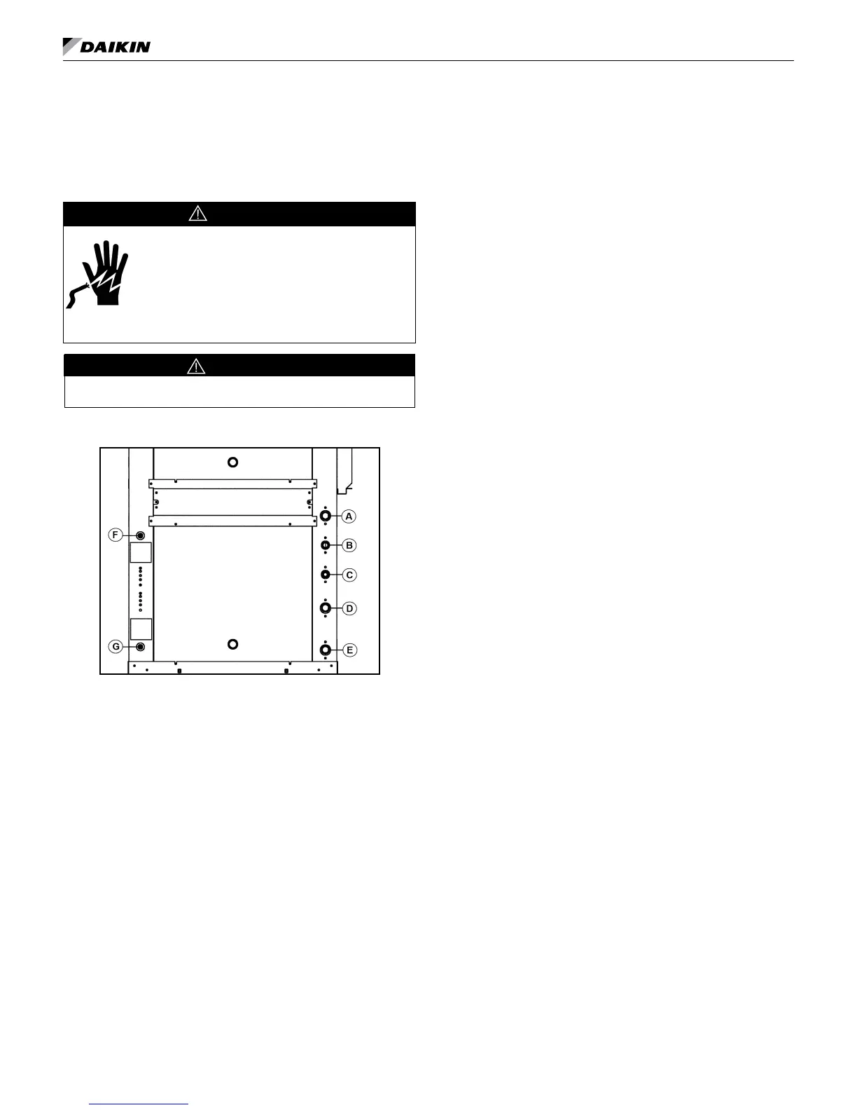
Figure 10: Unit Electrical and Piping Locations
ControlAccessPanel
A Condensate
B DesuperheaterWaterReturn(Optional)
C DesuperheaterWaterSupply(Optional)
D WaterReturn
E WaterSupply
F LowVoltageControlWiring(ElectricEntrance)
G LineVoltageUnitPower(ElectricEntrance)
Operating Voltages
115/60/1 .........104voltsmin.;127voltsmax.
208-230/60/1 .....197voltsmin.;253voltsmax.
265/60/1 . . . . . . . . .238voltsmin.;292voltsmax.
460/60/3 . . . . . . . . .414voltsmin.;506voltsmax.
575/60/3 . . . . . . . . .515voltsmin.;632voltsmax.
Note: Voltages listed are to show voltage range. How-
ever, units operating with over voltage and under
voltage for extended periods of time will experi-
ence premature component failure. Three phase
system unbalance should not exceed 2%.
General
1. Verifythecompatibilitybetweenthevoltageand
phaseoftheavailablepowerandthatshownonthe
unitdataplate.Lineandlowvoltagewiringmust
complywithlocalcodesortheNationalElectrical
Code,whicheverapplies.
2. Applycorrectlinevoltagetotheunit.A7⁄8"(22mm)
hole.Adisconnectswitchneartheunitisrequired
bycode.Powertotheunitmustbesizedcorrectly
andhavedualelement(ClassRK5)fusesoran
HACRcircuitbreakerforbranchcircuitovercurrent
protection.Seethedataplateforcorrectratings.
3. Connectthethermostat/subbasewiringwiththe
power“off”totheunit.
230 Volt Operation
All208-230voltsingle-phaseandthree-phaseunits
arefactorywiredfor208voltoperation.For230phase
operation,thelinevoltagetaponthe24-volttransformer
mustbechanged.Disconnectandcaptheredlead
wireandinterchangeitwiththeorangeleadwireonthe
primaryofthe24-volttransformer.
Fan Assembly
Allfanmotorsaremulti-speedPSCoroptionalECM
(sizes019-070)typewithintegralmountingbracketsand
thermaloverloadprotection.Themotorisisolatedfrom
thefanhousingforminimumvibrationtransmission.PSC
Fanmotorshaveaterminalstriponthemotorbodyfor
simplemotorspeedchangewithoutgoingbacktothe
controlbox.See"ChangingPSCFanMotorSpeed"on
page21.
Allthefan/motorassemblieshavearemovableorice
ringonthehousingtoaccommodatemotorandfan
wheelremovalwithoutdisconnectingtheductwork.
Thefanhousingprotrudesthroughthecabinetallowing
adequatematerialforconnectionofexibleduct.Each
modelunitisshippedfromthefactoryformaximum
performanceandminimumsoundrequirements.Fan
soundlevelsandperformancecanbeaffectedby
externalstaticpressure.