ESIE98–06A
Part 1 – System Outline 1–47
3
1
4
5
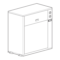
EUWA/Y15-20HC(Z)
terminal
connections
*: only EUWY.
Example
Item Code (contact) Description Terminals
1 L1/L2/L3/N/PE power supply to unit L1/L2/L3/N/PE
2 S12S mains isolator L1/L2/L3/N/PE
3 * S7S remote cool/heat setting 72-75
4 S8S dual set point 71-73
5 S9S remote start/stop 71-74
6 S10L/S11L flow switch / pump contact 72-76
7 KP pump contactor output 77-78
8 H1P remote alarm indication 79-80
9 H2P general operation indication 81-82
10 H3P circuit 1 operation indication 83-84
11 H4P circuit 2 operation indication 85-86
12 * H6P cool/heat indication 87-88
71 72 73 74 75 76 77 78 79 80 81 82 83 84 85 86 87 88
S2
S1
ON
OFF
H
C
FL
P
8 9 101113
~24 V to
~230 V
4536
7
S1 = set point 1
S2 = set point 2
ON = operation
OFF = no operation
H = heating
C = cooling
FL = flow switch
P = pump contact
~230 V
The numbers refer to the
items in the terminal
connections table.

 Loading...


