Instruction SiENBE04-512A
70 System Configuration
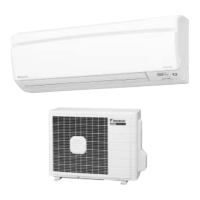
Outdoor Unit
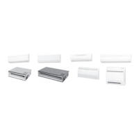
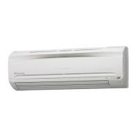
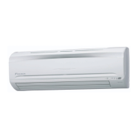
Indoor Unit
Outdoor Unit
Appearance of the outdoor unit may differ from some models.
19
22
20
21
18
17
1. Air filter
2. Airpurifying filter with photocatalytic
deodorizing function:
• These filters are attached to the inside of
the air filters.
3. Air inlet
4. Front panel
5. Panel tab
6. Room temperature sensor:
• It senses the air temperature around the
unit.
7. INTELLIGENT EYE sensor:
• It detects the movements of people and
automatically switches between normal
operation and energy saving operation.
(page18.)
8. Display
9. Air outlet
10. Flaps (horizontal blades):
(page 12.)
11. Louvers (vertical blades):
• The louvers are inside of the air outlet.
(Page 13.)
12. Indoor Unit ON/OFF switch:
• Push this switch once to start operation.
Push once again to stop it.
• the operation mode refers to the following
table..
• This switch is useful when the remote
control is missing.
13.Operation lamp (green)
14. TIMER lamp (yellow):
(page 20.)
15. HOME LEAVE lamp (red):
(page 16.)
16.Signal receiver:
• It receives signals from the remote control.
• When the unit receives a signal, you will
hear a short beep.
• Operation start................... beep-beep
• Settings changes............... beep
• Operation stop ................... beeeeep
17. Air inlet:
(Back and side)
18.Air outlet
19. Refrigerant piping and inter-unit cable
20. Drain hose
21. Earth terminal:
• It is inside of this cover.
22. Outside air temperature sensor:
• It senses the ambient temperature around
the unit.
Mode Temperature
setting
Air flow
rate
ATKS COOL 22°C AUTO
ATXS AUTO 25°C AUTO
SiENBE04-512A.book Page 70 Friday, October 5, 2007 1:49 PM
 Loading...