10
Installation Manual 3P291714-4
DCM601A72 iTM plus adaptor
English
The table below shows the status of the CPU ALIVE/ALARM LED when the iTM plus
adaptor is operating normally or failed.
NOTE
[LED status and operation table]
Operating condition CPU ALIVE ALARM
Normal Blink Off
Hardware failure Off On
Address failure On On
plus ADP IF communication failure On Blink
1.4 Determining installation place
Be sure to install the iTM plus adaptor in a place that meets the conditions described in
1.4.1 through 1.4.3.
1.4.1 Installation place and mounting direction
Note that the iTM plus adaptor must be installed in a place and in a mounting direction as
described below:
• Installation place: Indoor, inside control enclosure (which must be lockable or designed
to be opened only with a special tool)
• Mounting direction: Vertical only
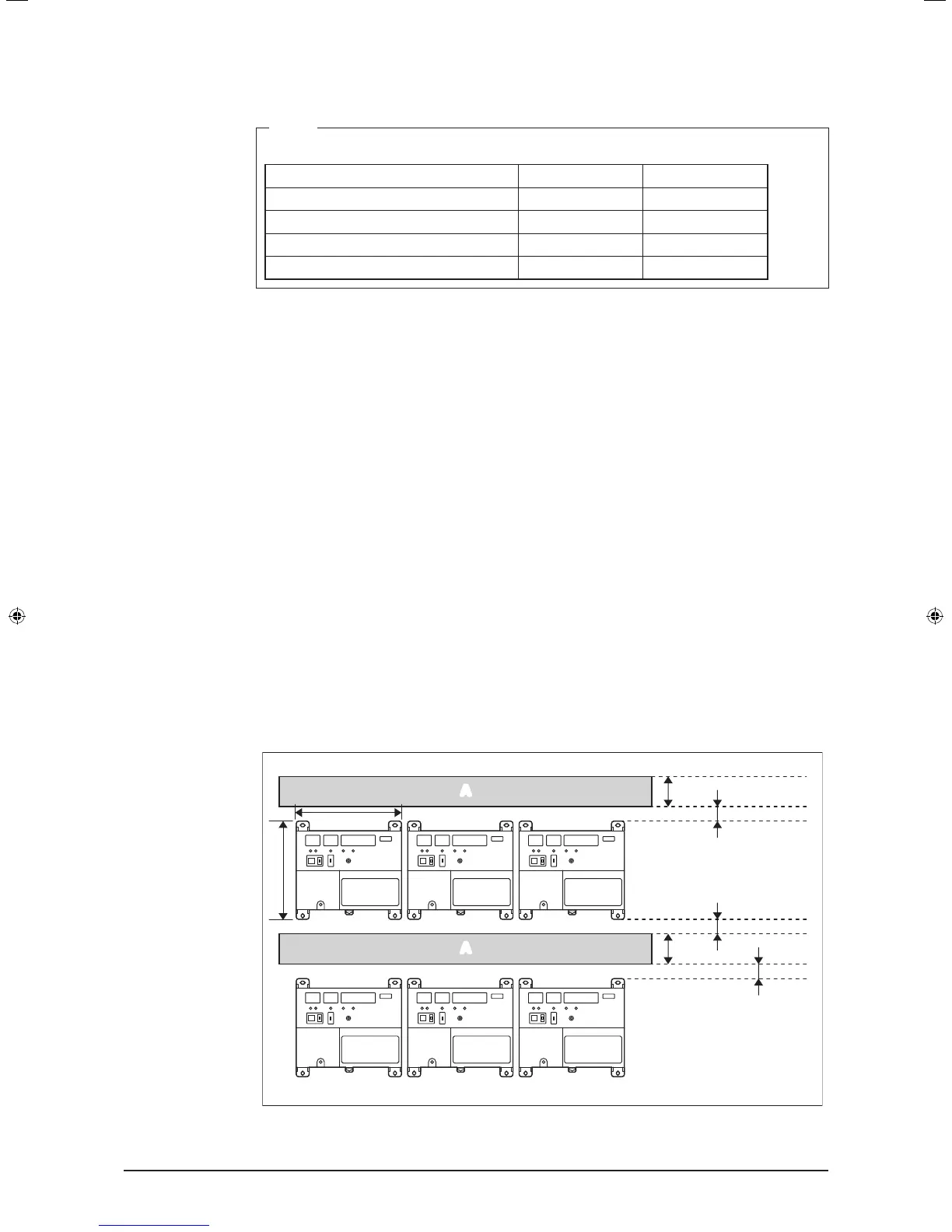
1.4.2 Required space
To install the iTM plus adaptor, the following space is required. Also note the following:
• Make sure that there is a minimum clearance of 25/32 in. between each unit and wiring
ducts.
• When installing two or more units side by side, they can be arranged without clearance
in the horizontal direction.
Required installa-
tion space
1-9/16
1-9/16
25/32
25/32
25/32
(in.)
A
A
6-5/16
5-7/8
A Wiring duct
01_EN_3P291714-4.indd 10 3/26/2012 5:00:45 PM