16
Installation Manual 3P291714-4
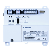
DCM601A72 iTM plus adaptor
English
2.2.1 Terminals location and conceptual connection diagram
To connect the DIII-NET communication line, use the two terminals F1 and F2 under the
label “DIII”. These 2 terminals have no polarity. An example of connecting more than 2 air
conditioning devices is shown in the following conceptual connection diagram.
CAUTION
Make sure that the wires you are connecting to the F1 and F2 terminals are not
power wires. Inadvertently connecting power wires to these terminals results in
a failure of the air conditioner or iTM plus adaptor.
<Conceptual connection diagram with air conditioning equipment>
F2F1
F1, F2 P1, P2 F1, F2 P1, P2F1, F2 P1, P2F1, F2 P1, P2F1, F2 P1, P2
F1, F2 F1, F2
F1, F2 P1, P2 F1, F2 P1, P2F1, F2 P1, P2F1, F2 P1, P2F1, F2 P1, P2
F1, F2 F1, F2
E
F
A
B C
D D D D D
A
B C
D D D D D
A Outdoor unit
B OUT - OUT
C IN - OUT
D Indoor unit
E A maximum of 16 indoor units can be connected per remote controller group.
F A maximum of 64 remote controller groups (128 indoor units) can be connected.
A maximum of 64 indoor units can be connected when power distribution is enabled.
01_EN_3P291714-4.indd 16 3/26/2012 5:00:45 PM