Installation Manual 3P291714-4
DCM601A72 iTM plus adaptor
13
2.1 Connecting intelligent Touch Manager
The iTM plus adaptor is a device that enables you to control more air conditioners with the
intelligent Touch Manager. It needs to be connected to an intelligent Touch Manager to
provide this capability.
2.1.1 Terminals location and conceptual connection diagram
Connect the terminals located in the “plus ADP IF” section of the iTM plus adaptor to the
corresponding terminals located in the “plus ADP IF” section on the rear face of your intel-
ligent Touch Manager. Note that these terminals have polarity. Be sure to connect the
positive wire to the “+” terminal and the negative wire to the “–” terminal, respectively.
In addition, the intelligent Touch Manager must be connected as a terminal to the wiring.
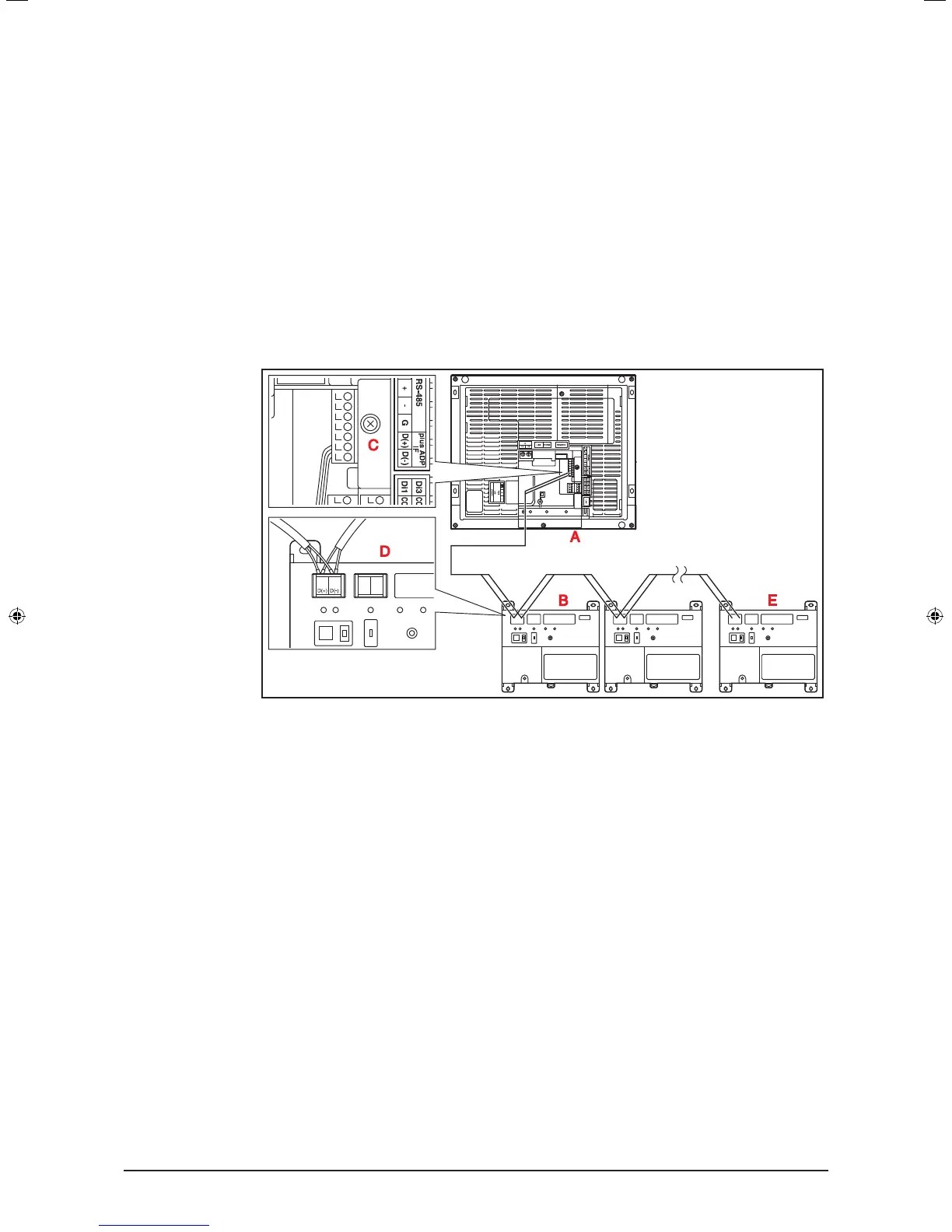
<Terminals location and conceptual connection diagram>
A intelligent Touch Manager (Rear face)
B iTM plus adaptor
C plus ADP IF (intelligent Touch Manager)
D plus ADP IF (iTM plus adaptor)
E iTM plus adaptor on which termination resistor must be enabled
2.1.2 Requirements that must be met
• Cable type: CPEV or FCPEV cable
• Core thickness: AWG22-19
• Cable length: 164 ft. or less in total for overall plus ADP IF wiring
01_EN_3P291714-4.indd 13 3/26/2012 5:00:45 PM