20
Installation Manual 3P291714-4
DCM601A72 iTM plus adaptor
English
2.4 Connecting power supply
Connect the iTM plus adaptor to an AC power supply.
WARNING
The following procedures must be carried out with the power supply shut off. Do
not turn the power supply on until all connections are made. Not doing so may
cause an electric shock.
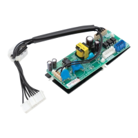
2.4.1 Terminals location and conceptual connection diagram
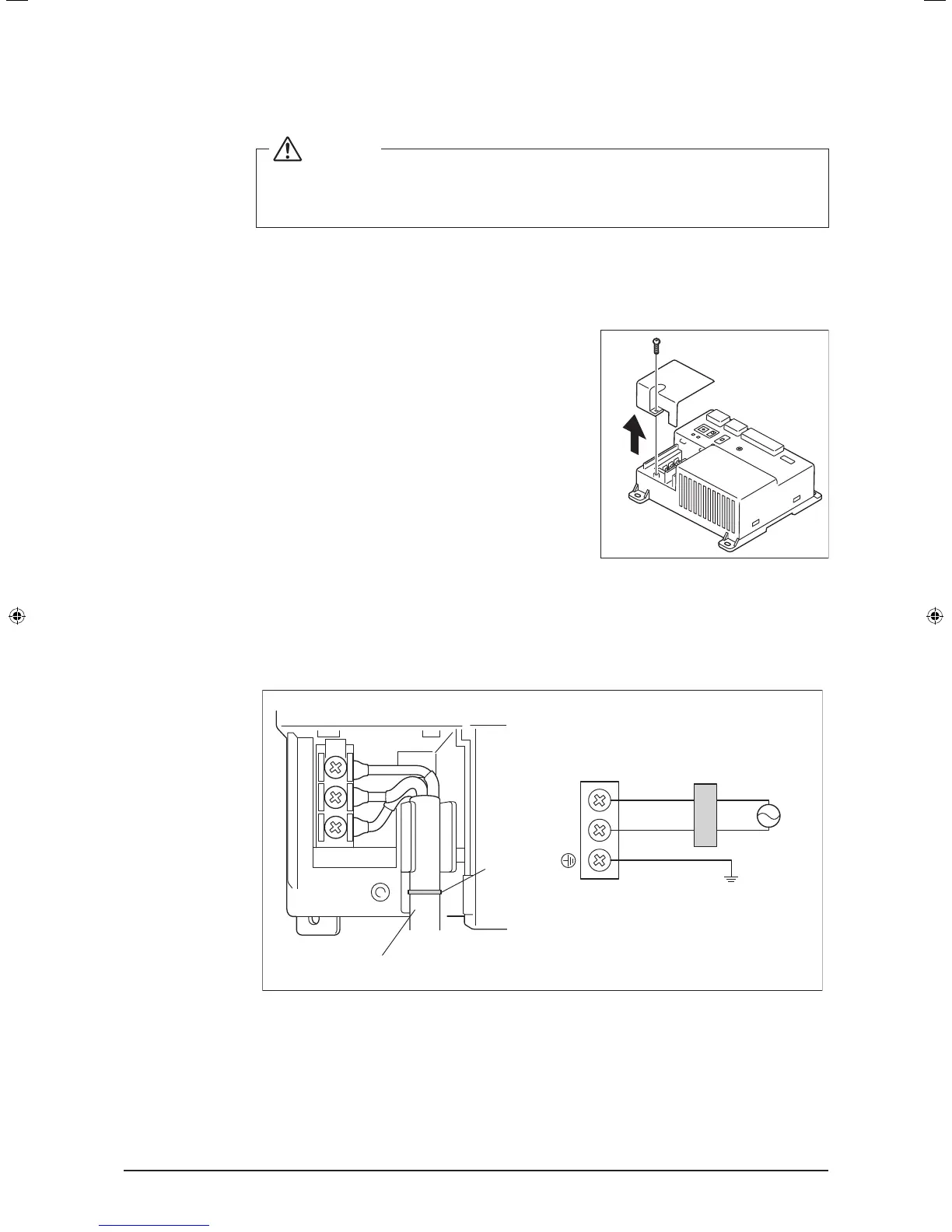
<Removing terminal cover>
For safety reasons, power connection terminals are
covered with a protective cover. Remove this cover
before you start connecting the power supply. You
can do so by loosening a single screw using a Phil-
lips screwdriver. The terminal cover must be replaced
where it was before when you nish connecting the
power supply.
Next, connect the power supply to the three terminals, L (Live), N (Neutral), and ground in
the POWER section. Be sure to ground the ground terminal. Remember to secure the
power cables to the blue resin cable mount with cable ties when power connections are
made.
<Connecting power supply>
D
B
LN
C
A
E
F
A Cable mount
B Earth leakage breaker
C Power supply (24VAC, 60Hz)
D Earth
E Secure cables with cable ties.
F Location of cable mount
01_EN_3P291714-4.indd 20 3/26/2012 5:00:46 PM