8
Installation Manual 3P291714-4
DCM601A72 iTM plus adaptor
English
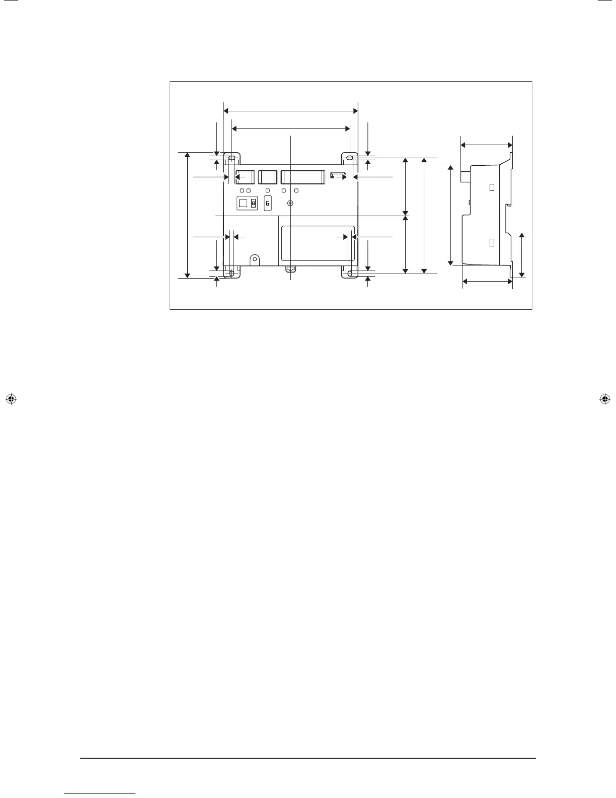
1.2 Understanding external dimensions
• iTM plus adaptor body
5-7/8
4-23/32
5-11/32
2-11/162-21/32
2-1/16
6-5/16
2-13/32
2-13/32
(in.)
1/4 1/4
5/32
5/32
1/4
5/32
1/4
5-1/2
5/32
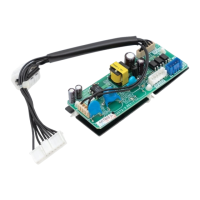
1.3 Understanding where terminals are located
Understand the arrangement of terminals and switches on the unit and draw up an ef-
cient work plan. For connection details including the cable type, terminal size, and wiring
precautions, refer to “2. Connection”.
1.3.1 Front face of iTM plus adaptor
All the terminals used during installation are located on the front face of the iTM plus
adaptor. Note that only the power terminals are covered with a terminal cover for safety.
You can remove this cover by loosening a single screw.
In addition to these terminals, several switches and LEDs are also located on the front
face of the iTM plus adaptor.
01_EN_3P291714-4.indd 8 3/26/2012 5:00:44 PM