ESIE16-03B | Part 5. Appendix 5.3. Wiring diagram
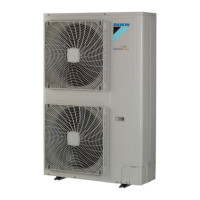
SA R32 Sky-Air RZAG-L
22/08/16 | Version 1.1 Page 115
5.3.2. Outdoor unit
Figure 5-2: Wiring diagram - outdoor unit 71
Legend
TC Signal transmission circuit
A1P Printed circuit board (main) V1D-V3D Diode
A2P Printed circuit board V1R IGBT power module
BS1-BS4 Push button switch V2R Diode module
C1-C3 Capacitor V1T, V2T Insulated Gate Bipolar Transistor (IGBT)
DS1 DIP switch X1M Terminal strip
E1H Bottom plate heater (option) Y1E Electronic expansion valve
F1U, F2U Fuse Y3E Electronic expansion valve
F6U Fuse (T 3.15 A / 250 V) Y1S Solenoid valve (4-way valve)
F7U, F8U Fuse (F 1.0 A / 250 V) Y2S Solenoid valve
H1P-H7P Light-emitting diode (service monitor is orange) Z1C-Z6C Noise filter (ferrite core)
HAP Light-emitting diode (service monitor is green) Z1F-Z3F Noise filter
K1R Magnetic relay (Y1S)
K2R Magnetic relay (Y2S)
Symbols
K2R, K10R Magnetic relay L Live
K11M Magnetic contactor N Neutral
K13R-K15R Magnetic relay Field wiring
L1R Reactor Terminal strip
M1C Motor (compressor) Terminal
M1F Motor (fan) Connector
PS Switching power supply Connection
01DI Earth leakage circuit breaker (30 mA) Protective earth
R2, R5, R6 Resistor Noiseless earth
R1T Thermistor (air) Option
R2T Thermistor (discharge)
R3T Thermistor (suction)
Colours
R4T Thermistor (heat exchanger inlet) BLK: Black
R5T Thermistor (heat exchanger middle) BLU: Blue
R6T Thermistor (liquid) BRN: Brown
R7T, R8T Thermistor (Positive Temperature Coefficient) GRN: Green
RC Signal receiver circuit PPL: Purple
S1PH-A Automatic high pressure switch RED: Red
S1PH-M Manual high pressure switch WHT: White
S1PL Low pressure switch YLW: Yellow
 Loading...
