ESIE16-03B | Part 5. Appendix 5.4. Piping diagram
SA R32 Sky-Air RZAG-L
22/08/16 | Version 1.1 Page 117
5.4. Piping diagram
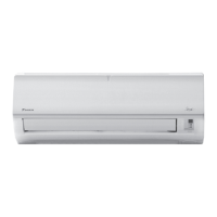
5.4.1. Indoor unit
Figure 5-4: Piping diagram - indoor unit
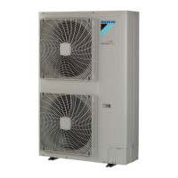
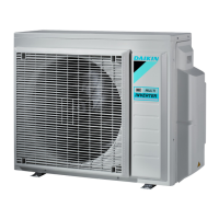
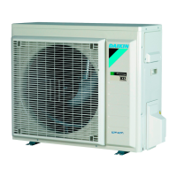
5.4.2. Outdoor unit
Figure 5-5: Piping diagram - outdoor unit
a. Liquid pipe connection b. Gas pipe connection c. Filter d. Heat exchanger
a. Field piping (liquid: 09.5 flare connection) M1C Motor (compressor)
b. Field piping (gas: 015.9 flare connection) R1T Thermistor (air)
c. Stop valve (with service port 5/16") R2T Thermistor (discharge)
d. Filter (4x) R3T Thermistor (suction)
e. Switch box cooling R4T Thermistor (heat exchanger inlet)
f. Pressure regulating valve R5T Thermistor (heat exchanger middle)
g. Heat exchanger R6T Thermistor (liquid)
h. Internal service port 5/16" S1PH-A Automatic high pressure switch
i. Check valve S1PH-M Manual high pressure switch
j. Compressor accumulator S1PL Low pressure switch
k. Liquid receiver Y1E Electronic expansion valve
l. Capillary tube Y3E Electronic expansion valve
Y1S Solenoid valve (4-way valve)
Y2S Solenoid valve
Heating
Cooling
 Loading...
