17 | Configuration
Installer and user reference guide
100
SV1A25AJV1B+SV4~8A14AJV1B
VRV 5 safety valve unit
4P749917-1 – 2023.09
17 Configuration
DANGER: RISK OF ELECTROCUTION
INFORMATION
It is important that all information in this chapter is read sequentially by the installer
and that the system is configured as applicable.
17.1 Making field settings
17.1.1 About making field settings
To configure the SV unit, you MUST give input to the SV unit's main PCBs (A1P and
A2P, depending on the unit). This involves the following field setting components:
▪ Push buttons to give input to the PCB
▪ A display to read feedback from the PCB
▪ DIP switches
The PCBs are located as shown below:
A1P Main PCB A1P
A2P Main PCB A2P (only for SV6~8A)
Note: Some field settings need to be made on all main PCBs (A1P and A2P) of the
same SV unit. For more information, see "17.1Making field settings"[4100].
Mode1 – monitoring settings
Mode1 can be used to monitor the current situation of the SV unit
Mode2 – field settings
Mode2 is used to change the field settings of the system. Consulting the current
field setting value and changing the current field setting value is possible.
In general, normal operation can be resumed without special intervention after
changing field settings.
17.1.2 To access the field setting components
See "14.3.1To open the unit"[468].
17.1.3 Field setting components
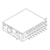
Location of the 7-segment displays and push buttons:
 Loading...
