13 | Special requirements for R32 units
Installer and user reference guide
48
SV1A25AJV1B+SV4~8A14AJV1B
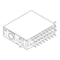
VRV 5 safety valve unit
4P749917-1 – 2023.09
0
10
20
30
40
50
70
90
110
80
60
100
5
10 20 30 40 50
2515 35 45
m [kg]
A
min
[m
2
]
No safety measure
(c)
Ventilated enclosure
OR
External alarm + natural ventilation
(f)
m Total refrigerant charge in the system [kg]
A
min
Minimum room area [m²]
(a) Lowest underground floor (=Lowest underground floor)
(b) All other floors (=All other floors)
(c) No safety measure (=No safety measure)
(d) External alarm OR Natural ventilation (=External alarm OR Natural ventilation)
(e) Ventilated enclosure (=Ventilated enclosure)
(f) Ventilated enclosure OR External alarm + natural ventilation (=Ventilated enclosure
OR External alarm + natural ventilation)
13.3.1 Overview: flowchart
Procedure to check required
countermeasure for SV unit
Determine area of room in which
SV unit is installed.
Determine total amount of
refrigerant in the system.
See Step
1 in above text
See Step
2 in above text
See Step
3 in
above text
See Step
3 in
above text
Determine required safety
measure based on ‘Lowest
underground floor’ of the graph
and table.
Determine required safety
measure based on ‘All other
floors’ of the graph and table.
A
[m²]
YESNO
SV unit installed on
lowest underground floor?
Ventilated enclosure
No safety measure
No safety measure
External alarm
Natural ventilation
External alarm +
Natural ventilation
Ventilated enclosure
Total charge amount [kg]
+
OR OR
Note: The flowchart is an overview. Always refer to the full text mentioned in this manual for clear understanding and detailed
explanation.
 Loading...
