18 | Commissioning
Installer and user reference guide
113
SV1A25AJV1B+SV4~8A14AJV1B
VRV 5 safety valve unit
4P749917-1 – 2023.09
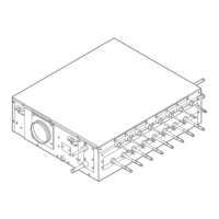
About measuring with a hot wire probe anemometer
▪ Attention: In case you need to drill holes in the ducting, choose a location
without thermal insulation.
▪ Where: Measure the airflow rate in the duct connected to the air outlet of the SV
unit.
▪ Postrequisite: Close the holes properly once the measurement is finished.
a SV unit
b Air outlet duct
c Direction airflow
d Hot wire probe anemometer
18.3.4 To perform a SV unit test run
See "17.1.8 Mode 2: field settings" [4 104] for more information on the settings
that are used.
Respect the sequence indicated in "18.3.1About the SV unit test run"[4110]. Do
not perform a test run on more than one SV unit at a time.
Prerequisite: All refrigerant piping work is finished.
1 Change field setting [2‑3] to "1". This setting simulates a refrigerant leak and
activates the safety measures according to the field settings that have been
made. See "18.3.1 About the SV unit test run" [4 110] to check which units
need a setting change.
2 In case of a configuration with an external alarm, check that the external
alarm warns both audibly (15dBA above the sound of the surroundings) and
visibly.
3 In case of a configuration with a ventilated enclosure, measure the airflow
rate. See "18.3.3 About measuring the airflow rate" [4 112] for more
information.
4 In all configurations, check if no safety measures are activated that are not
intended to activate.
5 Change field setting [2‑3] to "0". This setting deactivates the test run.
6 Change field setting [2‑6] to "1" for all SV units of the system, even those
where the test run was not activated (e.g. downstream SV units in a ventilated
enclosure series configuration). This setting confirms that the safety measures
are working correctly and - in the case of ventilated enclosure – it confirms
that the extraction airflow rate complies to the legal limits.
 Loading...
