16 | Electrical installation
Installer and user reference guide
96
SV1A25AJV1B+SV4~8A14AJV1B
VRV 5 safety valve unit
4P749917-1 – 2023.09
▪ Leave sufficient spare cable (±20 cm additionally) for all cables between the
fixation point inside the switch box and the fixation point on the side of the SV
unit. This spare cable is required to lower the switch box.
a Spare cable
b Switch box in upper position
c Switch box in lower position
7 Reattach the service cover. See "14.3.2To close the unit"[468].
CAUTION
Be careful NOT to pinch cables between the service cover and the switchbox.
16.3 To finish the electrical wiring
After installing the interconnection wiring, wrap it along with the onsite refrigerant
piping using finishing tape, as shown in the illustration below.
a Liquid piping
b Gas piping
c Finishing tape
d Interconnection cable (F1/F2)
e Insulation
16.4 To set the DIP switches
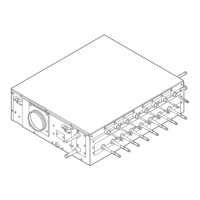
The DIP switches are located on the PCBs A1P, A2P (SV6~8A).
 Loading...
