15 | Piping installation
Installer and user reference guide
85
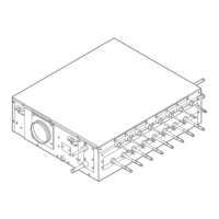
SV1A25AJV1B+SV4~8A14AJV1B
VRV 5 safety valve unit
4P749917-1 – 2023.09
c
d
b
a
Ø
6.35
mm
Ø
9.5
mm
Ø
12.7
mm
Ø
15.9
mm
Ø
9.5
mm
a Liquid branch pipe
b Gas branch pipe
c Liquid header pipe
d Gas header pipe
3 Connect the branch pipes. The liquid and gas branch pipe diameters to be
used depend on the connected indoor unit capacity class. For information on
which branch pipes to connect, see "To set the DIP switches when joining
branch pipe ports"[497].
4 Install stopper pipes (accessory) for unused header pipes (when the SV unit is
not connected in refrigerant flow-through with another SV unit) and unused
branch pipes (when no indoor unit is connected to that branch pipe port).
15.3.2 To braze the pipe end
DANGER: RISK OF BURNING/SCALDING
NOTICE
Precautions when connecting field piping. Add brazing material as shown in the
figure.
▪ When brazing, blow through with nitrogen to prevent creation of large quantities
of oxidised film on the inside of the piping. This film adversely affects valves and
compressors in the refrigerating system and prevents proper operation.
▪ Set the nitrogen pressure to 20kPa (0.2bar) (just enough so it can be felt on the
skin) with a pressure-reducing valve.
a Refrigerant piping
b Part to be brazed
c Taping
d Manual valve
e Pressure-reducing valve
f Nitrogen
▪ Do NOT use anti-oxidants when brazing pipe joints. Residue can clog pipes and
break equipment.
 Loading...
