17 | Configuration
Installer and user reference guide
107
SV1A25AJV1B+SV4~8A14AJV1B
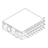
VRV 5 safety valve unit
4P749917-1 – 2023.09
The table below shows an example of address values assigned:
SV Main PCB Address value (e)
SV8A A1P 01
A2P -
SV6A A1P 02
A2P -
SV4A A1P 03
[2-9]
Setting to assign an address value to the SV unit for error handling.
Assign the same address to the main PCBs (A1P and A2P) of 1 SV unit, and another
address to the other SV units.
NOTICE
Field setting [2-9] is mandatory for all SV units and has to be made on all main PCBs
(A1P and A2P) of the SV unit.
[2-9]
(a)
Description
0 (default)~63 Address for error handling
(a)
Set on ALL main PCBs (A1P and A2P) of the SV unit.
Example
a
A2PA1P
e e
A2PA1P
e eb c
A1P
e
d
A1P Main PCB 1
A2P Main PCB 2
a Outdoor unit
b SV6A unit
c SV4A unit
d SV8A unit
e Address value for supervisor remote controller assigned to main PCB
Interconnection wiring
The table below shows an example of address values assigned:
SV Main PCB Address value (e)
SV8A A1P 1
A2P
SV6A A1P 2
A2P
SV4A A1P 3
[2-10]
Setting to enable or disable the external alarm output during the SV unit test run.
 Loading...
