13 | Special requirements for R32 units
Installer and user reference guide
57
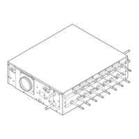
SV1A25AJV1B+SV4~8A14AJV1B
VRV 5 safety valve unit
4P749917-1 – 2023.09
d Extraction fan output terminal – connected
e Interconnection wiring terminal
f Extraction fan
A Outdoor unit A
B Outdoor unit B
Interconnection wiring
Extraction fan output wiring
An online tool (VRV Xpress) is available to find the required pressure capacity for
selecting the correct fan size. Only use this online tool for the calculation.
Field settings
Multiple SV units in parallel – one extraction fan
Code Description Value
[2-0]
(a)
Cluster indication 1: enable
[2-1]
(a)
Cluster number #
(b)
[2-2]
(a)
Cluster configuration 0 (default): parallel
[2-4]
(c)
Safety measures 1 (default): enable
[2-7]
(c)
Ventilated enclosure 1 (default): enable
(a)
Set on ALL main PCBs (A1P and A2P) of the SV unit.
(b)
Assign a unique cluster number to each cluster in the system. All SV units in the same
cluster MUST have the same cluster number.
(c)
Set ONLY on the LEFTMOST main PCB (A1P) of the SV unit.
Note: For more information, see "17.1Making field settings"[4100].
SV unit test run
Before SV unit operation, it is required to perform a test run that simulates a
refrigerant leak. See "18.3SV unit test run"[4110] for more details.
Multiple SV units in series – one extraction fan
In this configuration, multiple SV units are connected in series to a single extraction
fan. The air flows through every SV unit to the extraction fan. In case of a
refrigerant leak in any SV unit, the dampers of all SV units will open and allow air
evacuation to the extraction fan.
a SV unit
b Ductwork
c EKBSDCK
d Extraction fan
It is sufficient to connect the extraction fan circuit to only one SV unit of the cluster
(see "16.5 To connect the external outputs" [4 98]). It is not allowed to have SV
units in the same series cluster that belong to different outdoor unit systems.
Example
 Loading...
