6
20-06-2023
50400 >
In the event of new product developments, Dancutter reserves the right to change the technical description without advance notice.
Authorised Representative in the United Kingdom: Mini-Cam Limited Unit 33, Ravenscraig Road, Little Hulton, Salford, M38 9PU.
© Copyright 2021 Dancutter A/S. Dancutter A/S is a Halma Company. Dancutter A/S, Livøvej 1 A, DK-8800 Viborg, +45 9651 2150, info@dancutter.dk, dancutter.com
The screw hole for grease (GRS) Lubricate the piston
Congratulations
on your new
DC SUPER FLEX
To get the most satisfaction from your cutter, it is important that you
spend two minutes learning how to operate and maintain it.
Use an in-/external compressed air aftercooler.
Maximum water content per m
3
supply air:
20g/m
3
, (0,7 ounce/35 cfm)
For more information, read the attached user manual.
Before use
• Check that there is oil in the lubricating unit.
• NEVER bend the cutter outside of the pipe.
• The cutter operator is responsible for ensuring that the cutter is
handled safely, in and outside the pipe.
• The forward section must ALWAYS be closed together during
transport in and outside the pipe.
• Only use PURE AIR - WASHER FLUID W/ALCOHOL in the container
for camera cleaning.
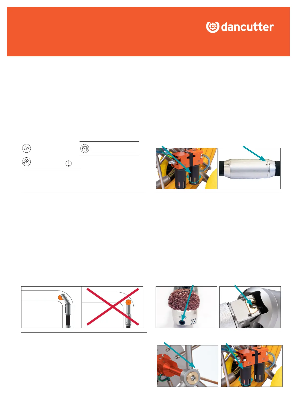
Check the oil
The forward section must ALWAYS
be closed together during transport
in and outside the pipe
Forcing a 90° bend
• Turn the cutter in the same direction as the bend.
• Raise the cutter arm.
• Push the cutter through.
• Lower the cutter arm.
• In the case of several bends, make a note and put tape on the hose,
so you know which way it shall face.
After use
• Clean the outside of the cutter with a water hose (not a high-pressure
cleaner) or compressed air.
• Clean the forward/back drive with compressed air. Fully extend the
unit and clean it in traces and edges with paper and cloth. (possibly
with a small screwdriver in the tracks).
• Raise the arm all the way and clean the hollow space behind the tilt
unit using compressed air. Next, lubricate the piston with oil and
re-lower the arm.
• UnscrewtheUnbrakoscrewintheendoftheGrinder(GRS),llthe
screw hole with blue grease and then re-attach.
As needed
• Lubricate the drum shaft with grease in the grease nipple.
• Checktheairlter(partnumberP57106)inthewaterseparatorto
be kept clean and changed as needed.
Grease in the grease nipple Airlter
AIR PREASSURE
10 BAR - 145 PSI
POWER SUPPLY
110/240 VAC - LN
AIR REQUIREMENT
650 L/MIN, (22 CFM)