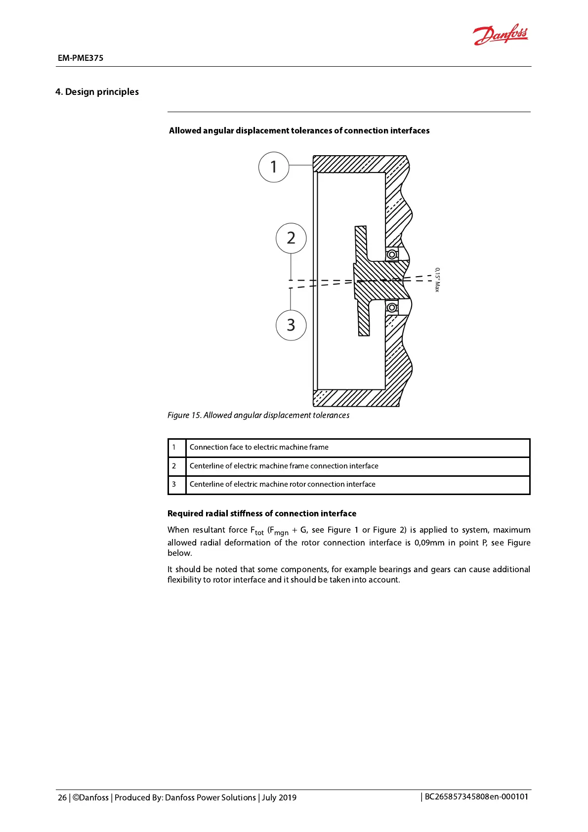
Allowed angular displacement tolerances of
connection interfaces
Figure 15. Allowed angular displacement tolerances
1 Connection face to electric machine frame
2 Centerline of electric machine frame connection interface
3 Centerline of electric machine rotor
connection interface
Required radial stiffness of connection interface
When resultant force F
tot
(F
mgn
+ G, see Figure 1 or Figure 2) is applied to system, maximum
allowed radial deformation of the
rotor connection interface is 0,09mm in point P, see Figure
below.
It should be noted that some components, for example
bearings and gears can cause additional
exibility to rotor interface and it should be taken into account.
 Loading...


