9
3.4 Top label
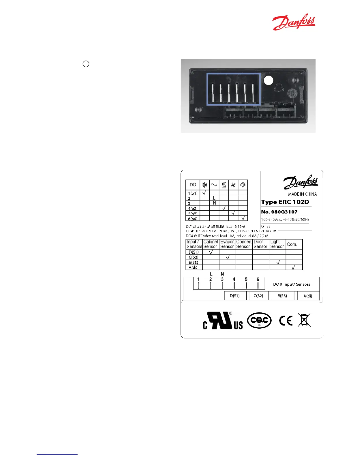
The illustration shows an example of a top label
affixed to an ERC 102D. The examples show what
is connected:
• Output 1 is used to switch the compressor
on and off.
• Outputs 2 and 3 are power – Live and Neutral.
• Output 4 is used to switch the heater on and off.
• Output 5 is used to switch the fan on and off.
• Output 6 is used to switch the light on and off.
• Input D (S1) is connected to a Cabinet Sensor to
measure temperature inside the cabinet.
• Input C(di) is used for Communications – a docking
station or KoolProg software running on a PC.
• Input B(S2) is connected to an Evaporator
Temperature Sensor.
• Input A(S3) is connected to an Ambient Light Sensor.
NOTE: Parameters depend on the code number sup-
plied. Please refer to the code number
specific technical drawing or use the KoolProg infor-
mation menu. For other applications,
a condenser sensor and a door sensor may
be used.
3.3 Connector outputs
All four outputs (
c
) are digitally controlled
on/off relays.
Functions controlled are:
• Compressor
• Pilot Relay
• Heater
• Defrost heater / valve for hot gas
• Alarm
• Fan
• Light
ERC 102 Reference manual – 3 OVERVIEW OF THE PRODUCT
C