FC 300 Profibus
How to Con figure the System
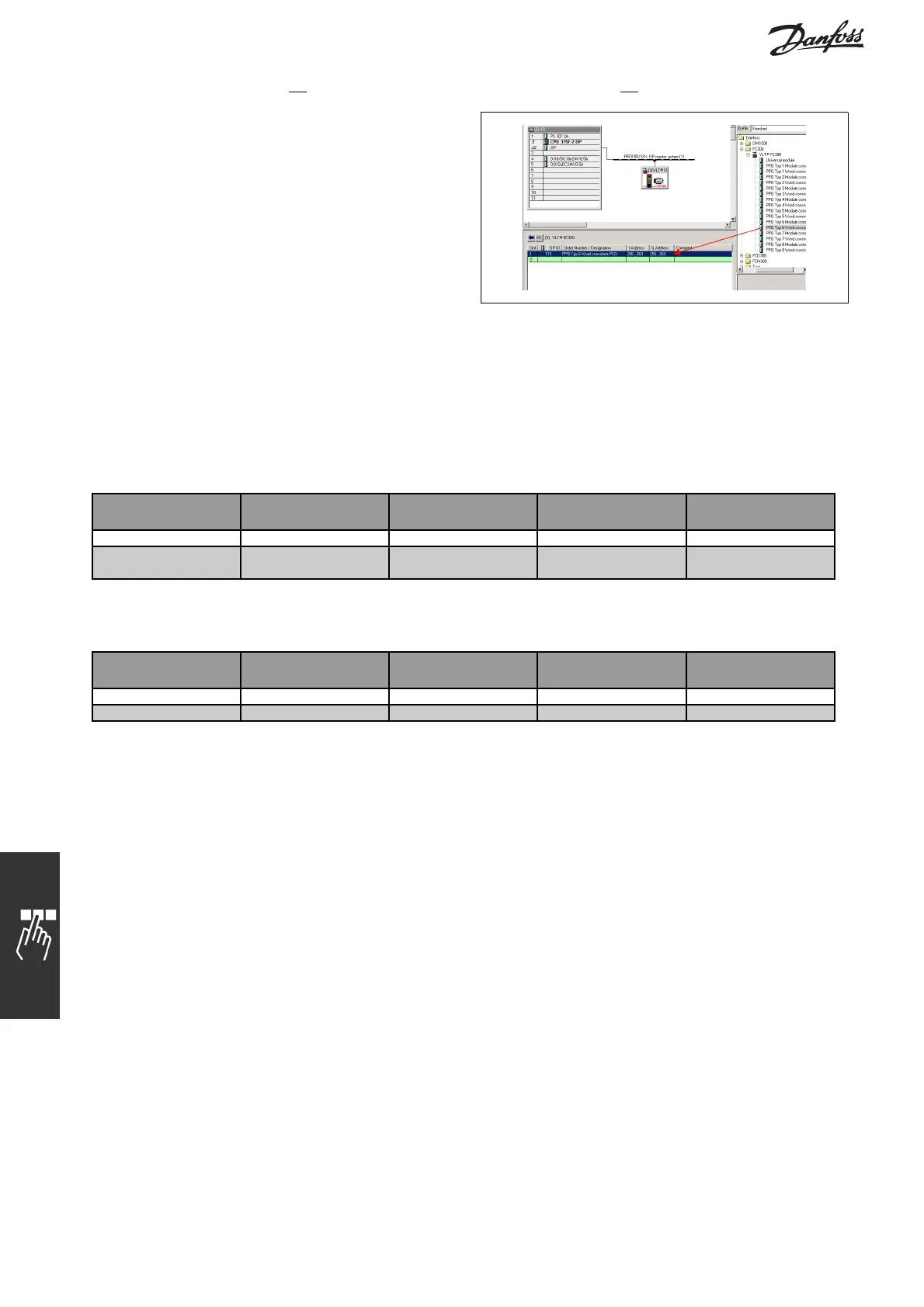
The next step is to set up the peripheral input and
output data. Data set up in the peripheral area is
transmitted cyclically via PPO types. In the example
below, a PPO type 6 Word consistent is dragged and
dropped to the first slot.
See the PPO types section in How to Control the FC
300 formoreinformation.
The configuration tool automatically assigns addresses in the peripheral address area. In this example the
input and output area have the following configuration:
PPO type 6:
PCD read (VLT to PLC)
PCD word
number
1 2 3 4
Input address 256-257 258-259 260-261 262-263
Set-up STW MAV Par. 9-16.2 Par. 9-16.3
PCD write (PLC to VLT)
PCD word
number
1 2 3 4
Output address 256-257 258-259 260-261 262-263
Set-up CTW MRV Par. 9-15.2 Par. 9-15.3
In PCDs 3 and 4 it is possible to assign Process signals. See an example of this in the Application Examples
chapter.
Download the configuration file to the PLC. The PROFIBUS system should be able to go online and it will start
to exchange data when the PLC is set to Run mode.
22
MG.33.C2.02 - VLT is a registered Danfoss trademark