4.2.5 IND
Some parameters in the frequency converter are array
parameters e.g. 3-10 Preset Reference. Since the Modbus
does not support arrays in the Holding registers, the
frequency converter has reserved the Holding register 9 as
pointer to the array. Before reading or writing an array
parameter, set the holding register 9. Setting holding
register to the value of 2, will cause all following read/
write to array parameters to be to the index 2.
4.2.6 Text Blocks
Parameters stored as text strings are accessed in the same
way as the other parameters. The maximum text block size
is 20 characters. If a read request for a parameter is for
more characters than the parameter stores, the response is
truncated. If the read request for a parameter is for fewer
characters than the parameter stores, the response is space
filled.
4.2.7
Conversion Factor
The different attributes for each parameter can be seen in
the section on factory settings. Since a parameter value
can only be transferred as a whole number, a conversion
factor must be used to transfer decimals.
4.2.8
Parameter Values
Standard data types
Standard data types are int16, int32, uint8, uint16 and
uint32. They are stored as 4x registers (40001–4FFFF). The
parameters are read using function 03HEX "Read Holding
Registers." Parameters are written using the function 6HEX
"Preset Single Register" for 1 register (16 bits), and the
function 10 HEX "Preset Multiple Registers" for 2 registers
(32 bits). Readable sizes range from 1 register (16 bits) up
to 10 registers (20 characters).
Non standard data types
Non standard data types are text strings and are stored as
4x registers (40001–4FFFF). The parameters are read using
function 03HEX "Read Holding Registers" and written using
function 10HEX "Preset Multiple Registers." Readable sizes
range from 1 register (2 characters) up to 10 registers (20
characters).
4.2.9
Modbus Exception Codes
For a full explanation of the structure of an exception code
response, refer to 4.2 Modbus TCP Message Framing
Structure.
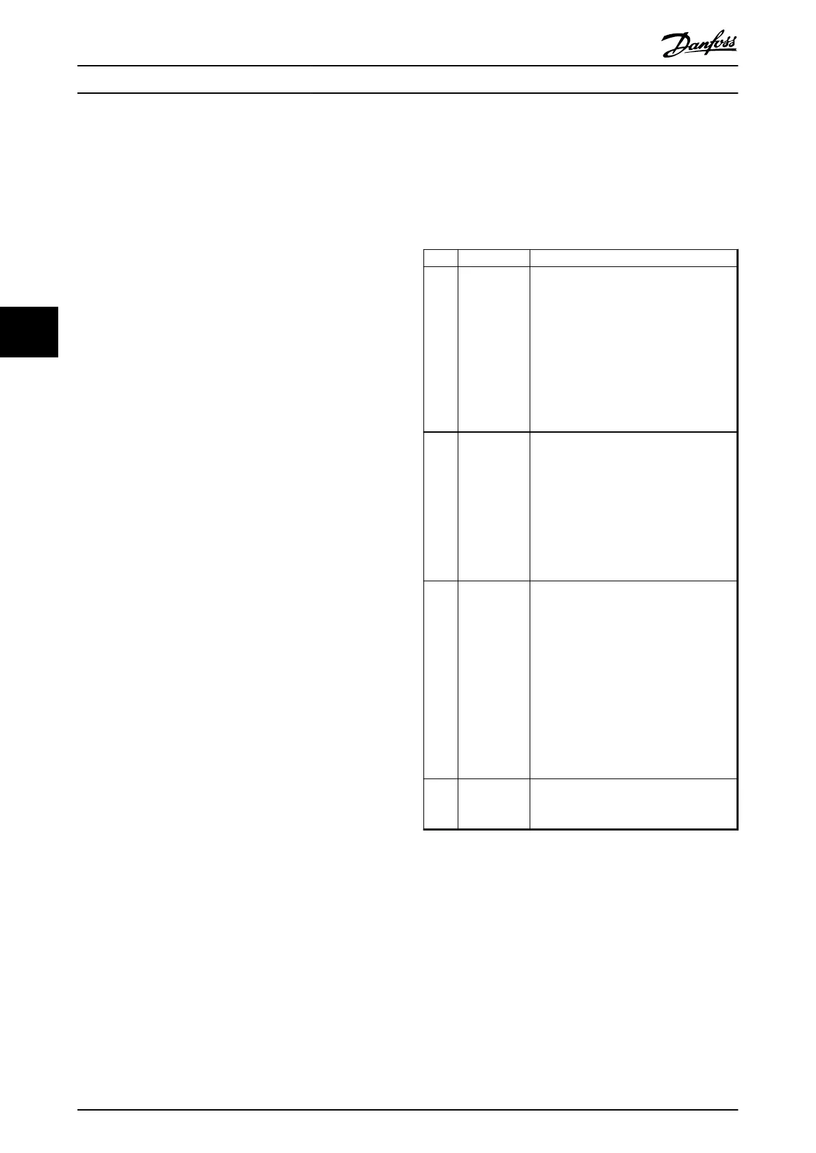
Code Name Meaning
1 Illegal
function
The function code received in the query is
not an allowable action for the server (or
slave). This may be because the function
code is only applicable to newer devices,
and was not implemented in the unit
selected. It could also indicate that the
server (or slave) is in the wrong state to
process a request of this type, for
example because it is not configured and
is being asked to return register values.
2 Illegal data
address
The data address received in the query is
not an allowable address for the server
(or slave). More specifically, the
combination of reference number and
transfer length is invalid. For a controller
with 100 registers, a request with offset
96 and length 4 would succeed, a request
with offset 96 and length 5 generates
exception 02.
3 Illegal data
value
A value contained in the query data field
is not an allowable value for server (or
slave). This indicates a fault in the
structure of the remainder of a complex
request, such as that the implied length is
incorrect. It specifically does NOT mean
that a data item submitted for storage in
a register has a value outside the
expectation of the application program,
since the Modbus protocol is unaware of
the significance of any particular value of
any particular register.
4 Slave device
failure
An unrecoverable error occurred while the
server (or slave) was attempting to
perform the requested action.
Table 4.3 Modbus Exception Codes
How to Control MCA 122 Modbus TCP
18 MG90P202 - VLT
®
is a protected Danfoss trademark
44