EasyManua.ls Logo

Danfoss MCA 122 Modbus TCP User Manual

Danfoss MCA 122 Modbus TCP
46 pages
To Next Page IconTo Next Page
To Previous Page IconTo Previous Page
Page #16 background image
NOTICE
The Ethernet Link Parameters are unique per port.
12-10 Link Status and 12-11 Link Duration displays
information on the link status, per port.
12-10 Link Status displays Link or No Link according to the
status of the present port.
12-11 Link Duration displays the duration of the link on the
present port. If the link is broken the counter resets.
12-12 Auto Negotiation is a feature that enables two
connected Ethernet devices to choose common
transmission parameters, such as speed and duplex mode.
In this process, the connected devices first share their
capabilities as for these parameters and then choose the
fastest transmission mode they both support.
By default this function is enabled.
Incapability between the connected devices, may lead to
decreased communication performance.
To prevent this, Auto Negotiation can be disabled.
If 12-12 Auto Negotiation is set to OFF, link speed and
duplex mode can be configured manually in 12-13 Link
Speed and 12-14 Link Duplex.
12-13 Link Speed displays/sets the link speed per port.
“None” is displayed if no link is present.
12-14 Link Duplex
displays/sets the duplex mode per
port.
Half-duplex provides communication in both directions,
but only in one direction at a time (not simultaneously).
Full-duplex allows communication in both directions, and
unlike half-duplex, allows for communication in both
directions, to happen simultaneously.
3.3 Configuring the Scanner
For configuring the scanner to communicate to the
frequency converter, no system (for example, EDS, GSD file)
file is needed. The frequency converter is handled as a
generic device and as such, configured directly in the
scanner. The following example sets up the scanner to IP
addresses 192.168.1.20 and the FC 302 to address
192.168.1.20.
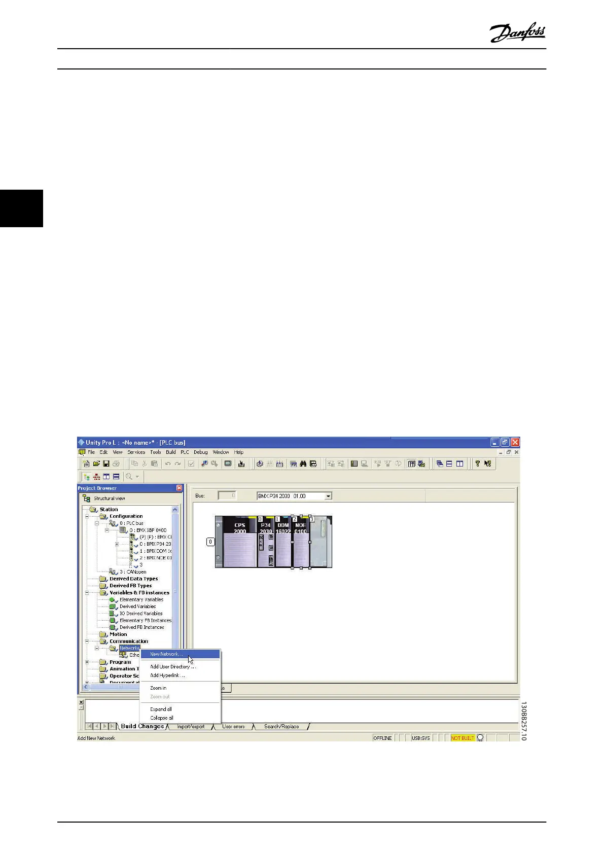
Configuring a Modicon scanner
The following example uses the Unity Pro tool from Group
Schneider to configure the PLC. The example only shows
the setting up of the Protocol and assigning I/O mapping
to internal memory of the PLC.
Under network, add a network by right clicking the
Network menu and select “New Network”
Illustration 3.1 Adding a Network
How to Configure MCA 122 Modbus TCP
12 MG90P202 - VLT
®
is a protected Danfoss trademark
33

Questions and Answers:

Danfoss MCA 122 Modbus TCP Specifications

General IconGeneral
BrandDanfoss
ModelMCA 122 Modbus TCP
CategoryDC Drives
LanguageEnglish

Summary

Safety

Copyright, Limitation of Liability and Revision Rights

Outlines Danfoss's copyright, liability limitations, and rights to revise the publication.

Safety Regulations

Lists mandatory safety practices and precautions for operating the frequency converter.

Warning Against Unintended Start

Details risks and precautions to prevent accidental starting of the motor.

Introduction

About This Manual

Provides essential information for quick installation and setup, and details for further study.

Assumptions and Background Knowledge

Outlines prerequisites, assumed knowledge, and scope of the manual for Modbus Option Card.

Available Literature and Modbus Conformance

Lists related documents and confirms compliance with Modbus standards.

Abbreviations

Lists and defines abbreviations used throughout the manual for clarity.

How to Install

The Modbus TCP Option

Details the installation of the MCA 122 Modbus TCP option into the frequency converter.

LED Behaviour and Status

Explains the function of the option's LEDs for module and network status.

Network Topology Options

Describes star and line topologies for connecting Modbus TCP options.

Network Design Rules

Covers Ethernet media selection, cable length, and design rules for reliable network operation.

EMC Precautions

Provides guidelines for minimizing electromagnetic interference for network operation.

How to Configure

IP Settings

Details parameters for configuring the option's IP address, subnet mask, and gateway.

Ethernet Link Parameters

Explains parameters related to the Ethernet link status, speed, and negotiation.

Configuring the Scanner

Guides on setting up a scanner (PLC) to communicate with the frequency converter.

IP Traffic Considerations

Discusses important aspects of IP traffic for industrial automation networks.

How to Control

Controlling the Frequency Converter

Explains how to control the frequency converter using Modbus TCP messages.

Modbus TCP Message Structure

Details the components and fields of a Modbus TCP message for communication.

Modbus Message Details

Covers IND, text blocks, conversion factors, parameter values, and exception codes.

PROFIdrive Control Profile

Describes the PROFIdrive control word (CTW) for sending commands to the slave.

PROFIdrive Status Word

Explains the PROFIdrive status word (STW) for notifying the master about the slave's status.

PROFIdrive State Diagram

Illustrates state transitions for the PROFIdrive control profile.

Reference Handling

Details how to manage speed references, including bus speed value scaling.

Danfoss FC Control Profile

Describes the control word for the Danfoss FC profile, including bits and explanations.

FC Status Word

Explains the FC status word (STW) for notifying the master about the frequency converter's status.

Parameters

Parameter Group 8-**

Details settings for control site, control word source, timeout functions, and end-of-timeout actions.

Parameter Group 12-**

Covers IP settings, Ethernet link parameters, process data, and Modbus TCP configurations.

Ethernet Services and Settings

Configures FTP, HTTP, SMTP services, cable diagnostics, and network storm protection.

Parameter List

Provides a comprehensive list of parameters with their default values and types.

Data Types and Conversion

Explains data types and provides a conversion index for parameters.

Troubleshooting

Step-by-Step Troubleshooting

Provides a guided approach to diagnose and resolve issues with LEDs, link status, cabling, and IP address.

Alarm and Warning Words

Explains how alarm and warning words are displayed and their meaning.

Related product manuals