EasyManua.ls Logo

Danfoss MCA 122 Modbus TCP User Manual

Danfoss MCA 122 Modbus TCP
46 pages
To Next Page IconTo Next Page
To Previous Page IconTo Previous Page
Page #28 background image
Bit 09, Selection of ramp 1/2
Bit 09=‘0’ means that ramp 1 is active (3-40 Ramp 1 Type to
3-47 Ramp 1 S-ramp Ratio at Decel. Start). Bit 09=‘1’ means
that ramp 2 (3-50 Ramp 2 Type to 3-57 Ramp 2 S-ramp Ratio
at Decel. Start) is active.
Bit 10, Data not valid/Data valid
Is used to tell the frequency converter whether the control
word is to be used or ignored. Bit 10=“0” causes the
control word to be ignored, giving the opportunity to turn
off the control word when updating/reading parameters.
Bit 10=“1” causes the control word to be used. This
function is relevant, because the control word is always
contained in the telegram, regardless of which type of
telegram is used.
Bit 11, Relay 01
Bit 11=‘0’ Relay not activated. Bit 11 = ‘1’ Relay 01
activated, provided Control word bit 11 has been chosen in
5-40 Function Relay.
Bit 12, Relay 02
Bit 12=‘0’ Relay 02 has not been activated.
Bit 12=‘1’ Relay 02 has been activated, provided Control
word bit 12 has been chosen in 5-40 Function Relay.
Bit 13/14, Selection of set-up
Bits 13 and 14 are used to select one of 4 menu set-ups
according to Table 4.9:
Set-up
Bit 14 Bit 13
1 0 0
2 0 1
3 1 0
4 1 1
Table 4.9 Menu Set-ups
The function is only possible when Multi-Set-ups is selected
in 0-10 Active Set-up.
NOTICE
In 8-55 Set-up Select a selection is made to define how Bit
13/14 gates with the corresponding function on the digital
inputs.
Bit 15 Reverse
Bit 15=‘0’ causes no reversing.
Bit 15=‘1’ causes reversing.
NOTICE
In the factory setting reversing is set to digital in
8-54 Reversing Select. Bit 15 causes reversing only when Ser.
communication, Logic AND or Logic OR is selected.
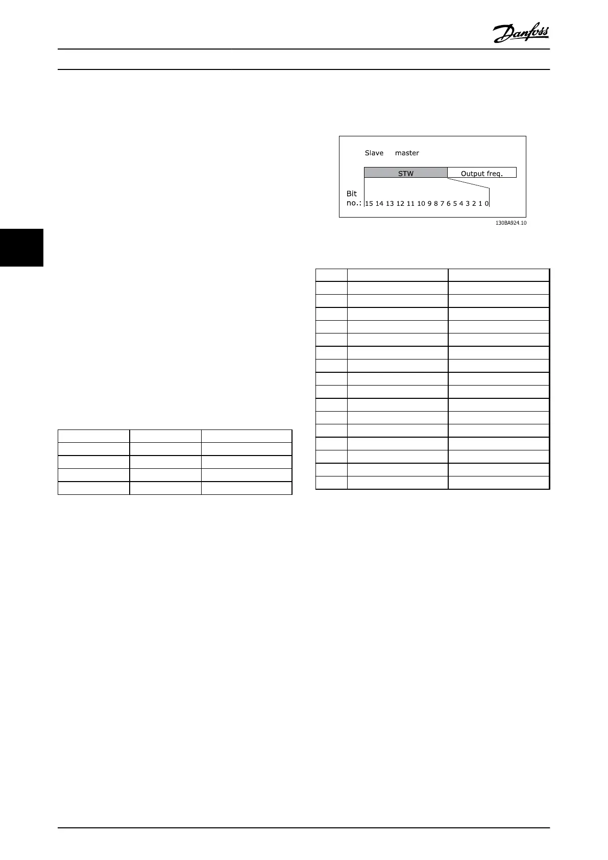
4.4.1 Status Word according to Frequency
Converter Profile (STW)
Illustration 4.3 8-10 Control Word Profile
Bit Bit value=0 Bit value=1
00 Control not ready Control ready
01 Drive not ready Drive ready
02 Coasting Enable
03 No error Trip
04 No error Error (no trip)
05 Reserved -
06 No error Trip lock
07 No warning Warning
08 Speed reference Speed = reference
09 Local operation Bus control
10 Out of frequency limit Frequency limit ok
11 No operation In operation
12 Drive ok Stopped, auto start
13 Voltage ok Voltage exceeded
14 Torque ok Torque exceeded
15 Thermal ok Thermal exceeded
Table 4.10 Staus Word Bits
Explanation of the status bits
Bit 00, Control ready
Bit 00=‘0’ means that the frequency converter has tripped.
Bit 00=‘1’ means that the frequency converter controls are
ready, but that the power component is not necessarily
receiving any power supply (in the event of external 24 V
supply to controls).
Bit 01, Drive ready
Bit 01=‘1’. The frequency converter is ready for operation.
Bit 02, Coasting stop
Bit 02=‘0’. The frequency converter has released the motor.
Bit 02=‘1’. The frequency converter can start the motor
when a start command is given.
Bit 03, No error/Trip
Bit 03=‘0’ means that the frequency converter is not in
fault mode.
Bit 03=‘1’ means that the frequency converter is tripped,
and that a reset signal is required to re-establish operation.
Bit 04, No error/Error (no trip)
Bit 04=‘0’ means that the frequency converter is not in
fault mode.
How to Control MCA 122 Modbus TCP
24 MG90P202 - VLT
®
is a protected Danfoss trademark
44

Questions and Answers:

Danfoss MCA 122 Modbus TCP Specifications

General IconGeneral
BrandDanfoss
ModelMCA 122 Modbus TCP
CategoryDC Drives
LanguageEnglish

Summary

Safety

Copyright, Limitation of Liability and Revision Rights

Outlines Danfoss's copyright, liability limitations, and rights to revise the publication.

Safety Regulations

Lists mandatory safety practices and precautions for operating the frequency converter.

Warning Against Unintended Start

Details risks and precautions to prevent accidental starting of the motor.

Introduction

About This Manual

Provides essential information for quick installation and setup, and details for further study.

Assumptions and Background Knowledge

Outlines prerequisites, assumed knowledge, and scope of the manual for Modbus Option Card.

Available Literature and Modbus Conformance

Lists related documents and confirms compliance with Modbus standards.

Abbreviations

Lists and defines abbreviations used throughout the manual for clarity.

How to Install

The Modbus TCP Option

Details the installation of the MCA 122 Modbus TCP option into the frequency converter.

LED Behaviour and Status

Explains the function of the option's LEDs for module and network status.

Network Topology Options

Describes star and line topologies for connecting Modbus TCP options.

Network Design Rules

Covers Ethernet media selection, cable length, and design rules for reliable network operation.

EMC Precautions

Provides guidelines for minimizing electromagnetic interference for network operation.

How to Configure

IP Settings

Details parameters for configuring the option's IP address, subnet mask, and gateway.

Ethernet Link Parameters

Explains parameters related to the Ethernet link status, speed, and negotiation.

Configuring the Scanner

Guides on setting up a scanner (PLC) to communicate with the frequency converter.

IP Traffic Considerations

Discusses important aspects of IP traffic for industrial automation networks.

How to Control

Controlling the Frequency Converter

Explains how to control the frequency converter using Modbus TCP messages.

Modbus TCP Message Structure

Details the components and fields of a Modbus TCP message for communication.

Modbus Message Details

Covers IND, text blocks, conversion factors, parameter values, and exception codes.

PROFIdrive Control Profile

Describes the PROFIdrive control word (CTW) for sending commands to the slave.

PROFIdrive Status Word

Explains the PROFIdrive status word (STW) for notifying the master about the slave's status.

PROFIdrive State Diagram

Illustrates state transitions for the PROFIdrive control profile.

Reference Handling

Details how to manage speed references, including bus speed value scaling.

Danfoss FC Control Profile

Describes the control word for the Danfoss FC profile, including bits and explanations.

FC Status Word

Explains the FC status word (STW) for notifying the master about the frequency converter's status.

Parameters

Parameter Group 8-**

Details settings for control site, control word source, timeout functions, and end-of-timeout actions.

Parameter Group 12-**

Covers IP settings, Ethernet link parameters, process data, and Modbus TCP configurations.

Ethernet Services and Settings

Configures FTP, HTTP, SMTP services, cable diagnostics, and network storm protection.

Parameter List

Provides a comprehensive list of parameters with their default values and types.

Data Types and Conversion

Explains data types and provides a conversion index for parameters.

Troubleshooting

Step-by-Step Troubleshooting

Provides a guided approach to diagnose and resolve issues with LEDs, link status, cabling, and IP address.

Alarm and Warning Words

Explains how alarm and warning words are displayed and their meaning.

Related product manuals