Long control cables and analog signals may, in rare cases,
and depending on installation, result in 50/60 Hz ground
loops due to noise from line power supply cables.
If ground loops occur, it may be necessary to break the
shield or insert a 100 nF capacitor between shield and
enclosure.
Connect the digital and analog inputs and outputs
separately to the adjustable frequency drive common
inputs (terminal 20, 55, 39) to avoid ground currents from
both groups to aect other groups. For example, switching
on the digital input may disturb the analog input signal.
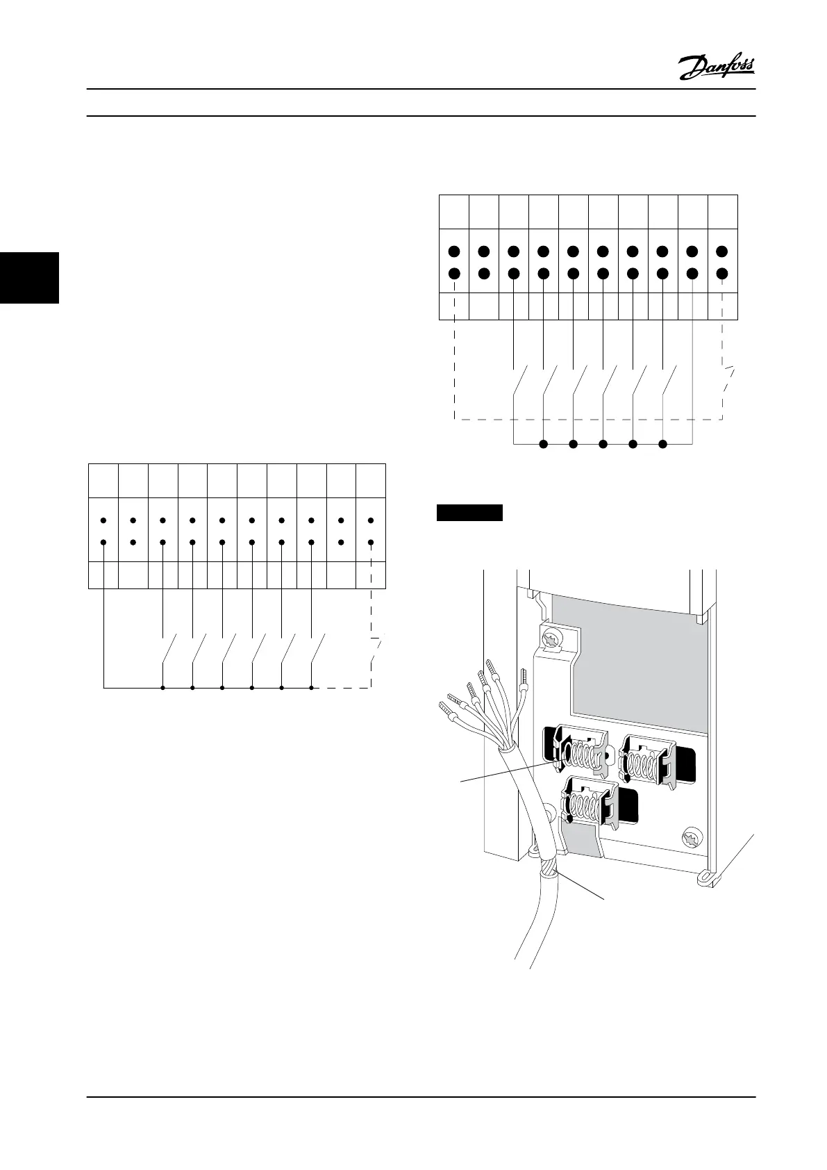
Input polarity of control terminals
12 13 18 19 27 29 32 33 20 37
+24 V DC
0 VDC
130BT106.10
PNP (Source)
Digital input wiring
Figure 4.23 PNP Polarity
NPN (Sink)
Digital input wiring
12 13 18 19 27 29 32 33 20 37
+24 V DC
0 VDC
130BT107.11
Figure 4.24 NPN Polarity
NOTICE!
Control cables must be shielded/armored.
Figure 4.25 Shielded Control Cable
Connect the wires as described. To ensure optimum
electrical immunity, connect the shields properly.
Electrical Installation
VLT
®
HVAC Drive FC 102
60 Danfoss A/S © 08/2014 All rights reserved. MG11F522
44
 Loading...


