4.1.21 Switches S201, S202 and S801
Use switches S201 (A53) and S202 (A54) to congure the
analog input terminals 53 and 54 as a current (0–20 mA)
or a voltage (-10 V to +10 V).
Enable termination on the RS-485 port (terminals 68 and
69) via the switch S801 (BUS TER.).
See Figure 4.21.
Default setting:
S201 (A53) = OFF (voltage input)
S202 (A54) = OFF (voltage input)
S801 (Bus termination) = OFF
NOTICE!
When changing the function of S201, S202, or S801, do
not to use force during the switch over. Remove the LCP
xture (cradle) when operating the switches. Do not
operate the switches when the adjustable frequency
drive is powered.
Figure 4.26 Switch Location
4.2
Connection Examples
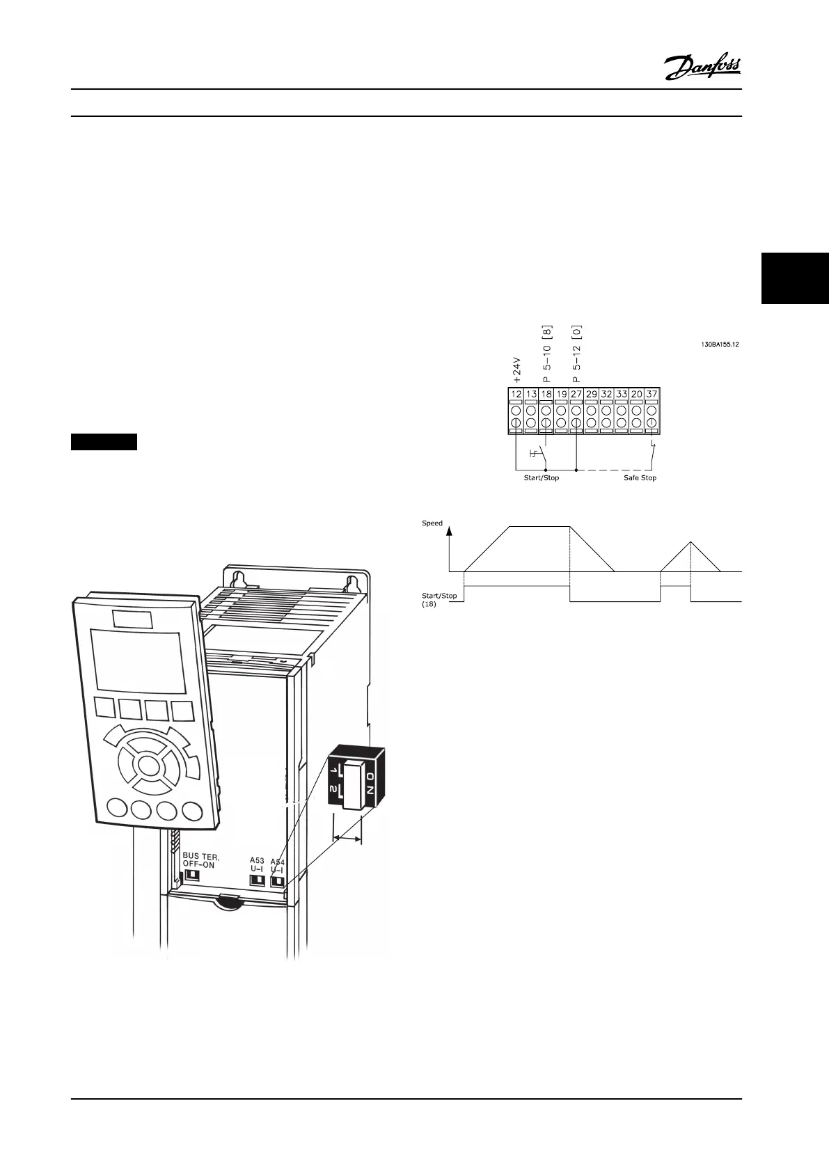
4.2.1 Start/Stop
Terminal 18 = parameter 5-10 Terminal 18 Digital Input [8]
Start
Terminal 27 = parameter 5-12 Terminal 27 Digital Input [0]
No operation (Default coast inverse)
Terminal 37 = STO
Figure 4.27 Wiring Start/Stop
Electrical Installation Instruction Manual
MG11F522 Danfoss A/S © 08/2014 All rights reserved. 61
4 4
 Loading...


