4.3 Final Set-up and Test
To test the set-up and to ensure that the adjustable
frequency drive is running, follow these steps.
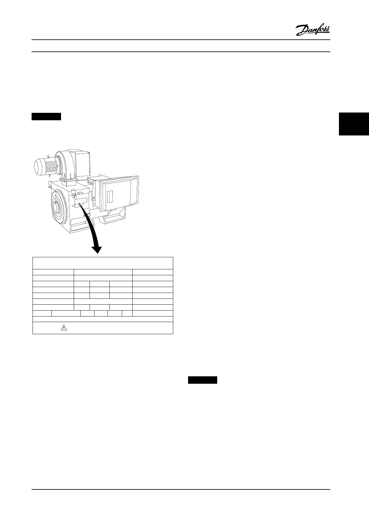
Step 1. Locate the motor nameplate.
NOTICE!
The motor is either star (Y) or delta connected (Δ). This
information is on the motor nameplate.
THREE PHASE INDUCTION MOTOR
kW
400
MOD
MCV 315E
Nr.
135189 12 04
PRIMARY
SECONDARY
V
690
A
V A
V A
V A
410.6 CONN Y
CONN
CONN
CONN ENCLOSURE
CAUTION
COS f
ALT
RISE
m
SF
1.15
0.85
AMB
40
1000
80
°C
°C
IP23
40
IL/IN
6.5
HP
536
mm
1481
Hz
DESIGN
50
N
DUTY
INSUL WEIGHT 1.83 ton
EFFICIENCY %
95.8% 95.8% 75%100%
S1
I
130BA767.10
Figure 4.31 Nameplate
Step 2. Enter the motor nameplate data in this
parameter list.
To access this list, press [Quick Menu], then select Q2 Quick
Set-up ”Quick".
1.
Parameter 1-20 Motor Power [kW]
Parameter 1-21 Motor Power [HP]
2.
Parameter 1-22 Motor Voltage
3.
Parameter 1-23 Motor Frequency
4.
Parameter 1-24 Motor Current
5.
Parameter 1-25 Motor Nominal Speed
Step 3. Activate the Automatic Motor Adaptation (AMA).
Performing an AMA ensures optimum performance. The
AMA measures the values from the motor model
equivalent diagram.
1. Connect terminal 37 to terminal 12 (if terminal 37
is available).
2. Connect terminal 27 to terminal 12 or set
parameter 5-12 Terminal 27 Digital Input to [0] No
function.
3.
Activate the AMA parameter 1-29 Automatic Motor
Adaptation (AMA).
4. Select between complete or reduced AMA. If a
sine-wave lter is mounted, run only the reduced
AMA, or remove the sine-wave lter during the
AMA procedure.
5.
Press [OK]. The display shows Press [Hand On] to
start.
6. Press [Hand On]. A progress bar indicates if the
AMA is in progress.
Stop the AMA during operation
1. Press [O]. The adjustable frequency drive enters
into alarm mode and the display shows that the
user terminated the AMA.
Successful AMA
1.
The display shows Press [OK] to nish AMA.
2. Press [OK] to exit the AMA state.
Unsuccessful AMA
1. The adjustable frequency drive enters into alarm
mode. A description of the alarm can be found
in .
2.
Report Value in the [Alarm Log] shows the last
measuring sequence carried out by the AMA
before the adjustable frequency drive entered
alarm mode. This number along with the
description of the alarm helps with trouble-
shooting. State the alarm number and description
when contacting Danfoss service.
NOTICE!
Incorrectly registered motor nameplate data, or a
dierence between the motor power size and the
adjustable frequency drive power size that is too large
often causes unsuccessful AMA.
Step 4. Set the speed limit and ramp time.
•
Parameter 3-02 Minimum Reference
•
Parameter 3-03 Maximum Reference
Electrical Installation
Instruction Manual
MG11F522 Danfoss A/S © 08/2014 All rights reserved. 63
4 4
 Loading...


