compensating for the changing resistance in the primary piping loop as chillers and their pumps are staged on
and o.
•
The operator can use local speed determination by decreasing the output frequency until the design ow rate is
achieved. Using a drive to decrease the pump speed is similar to trimming the pump impeller, but more ecient.
The balancing contractor simply decreases the speed of the pump until the proper ow rate is achieved and leaves
the speed xed. The pump operates at this speed any time the chiller is staged on. Because the primary loop lacks
control valves or other devices that can change the system curve, and the variance due to staging pumps and
chillers on and o is small, this xed speed remains appropriate. If the ow rate must be increased later in the life
of the system, the drive can simply increase the pump speed instead of requiring a new pump impeller.
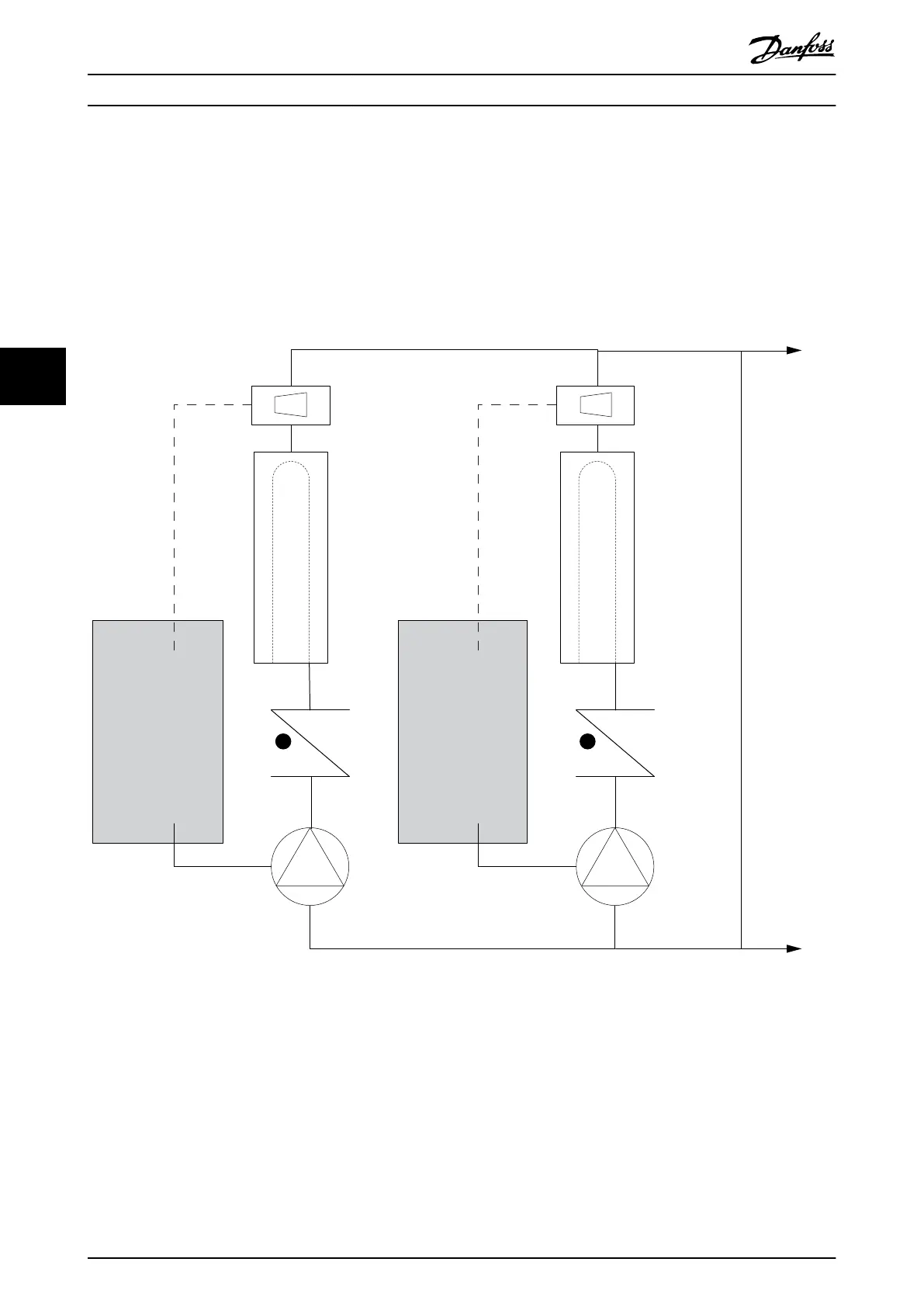
Frequency
converter
Frequency
converter
CHILLER
CHILLER
Flowmeter
Flowmeter
F F
130BB456.10
Illustration 5.20 Drives Used with Primary Pumps in a Primary/Secondary Pump System
For more information, consult the Danfoss supplier for the Primary Pumps: Improving Primary Pumping in Pri/Sec System
application note.
Product Features
VLT
®
HVAC Drive FC 102
36 Danfoss A/S © 11/2017 All rights reserved. MG16C302
55
 Loading...


