VLT
®
HVAC Drive FC 102
P1M0 P1M2 P1M4
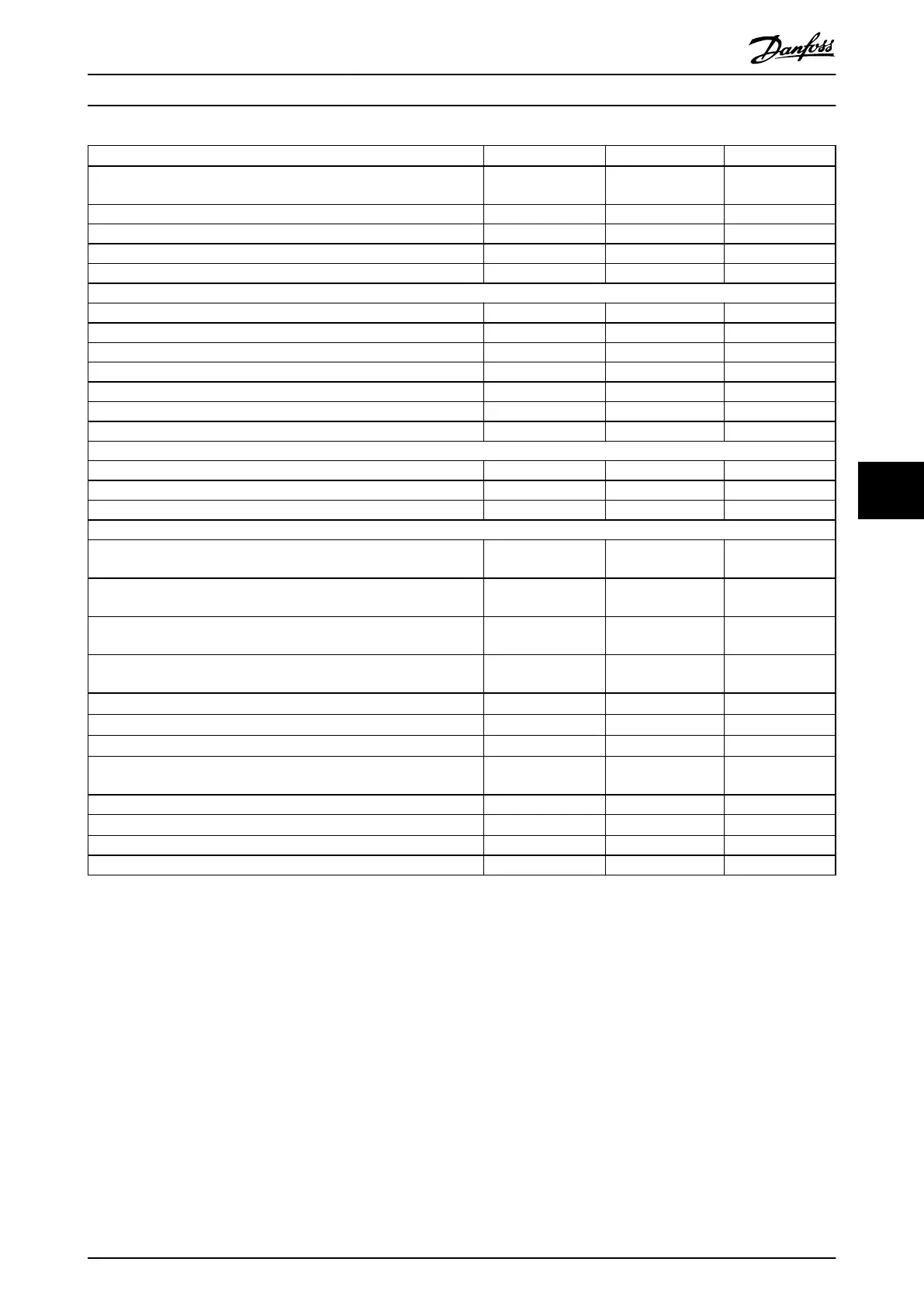
Normal overload NO NO NO
(Normal overload=110% current during 60 s)
Typical shaft output at 550 V [kW] 850 1000 1100
Typical shaft output at 575 V [hp] 1150 1350 1550
Typical shaft output at 690 V [kW] 1000 1200 1400
Enclosure size F12/F13 F12/F13 F12/F13
Output current (3-phase)
Continuous (at 550 V) [A] 1108 1317 1479
Intermittent (60 s overload) (at 550 V) [A] 1219 1449 1627
Continuous (at 575/690 V) [A] 1060 1260 1415
Intermittent (60 s overload) (at 575/690 V) [A] 1166 1386 1557
Continuous kVA (at 550 V) [kVA] 1056 1255 1409
Continuous kVA (at 575 V) [kVA] 1056 1255 1409
Continuous kVA (at 690 V) [kVA] 1267 1506 1691
Maximum input current
Continuous (at 550 V) [A] 1068 1269 1425
Continuous (at 575 V) [A] 1022 1214 1364
Continuous (at 690 V) [A] 1022 1214 1364
Maximum number and size of cables per phase
- Motor [mm
2
(AWG)]
12x150 (12x300
mcm)
12x150 (12x300
mcm)
12x150 (12x300
mcm)
- Mains [mm
2
(AWG)] (F12)
8x240 (8x500 mcm) 8x240 (8x500 mcm) 8x240 (8x500
mcm)
- Mains [mm
2
(AWG)] (F13)
8x456 (8x900 mcm) 8x456 (8x900 mcm) 8x456 (8x900
mcm)
- Brake [mm
2
(AWG)]
6x185 (6x350 mcm) 6x185 (6x350 mcm) 6x185 (6x350
mcm)
Maximum external mains fuses [A]
1)
1600 2000 2500
Estimated power loss at 600 V [W]
2), 3)
13731 16190 18536
Estimated power loss at 690 V [W]
2), 3)
14250 16821 19247
Maximum added losses for circuit breaker or disconnect and contactor
[W], (F13 only)
665 863 1044
Maximum panel options losses [W] 400 400 400
Eciency
3)
0.98 0.98 0.98
Output frequency [Hz] 0–500 0–500 0–500
Control card overtemperature trip [°C (°F)]
85 (185) 85 (185) 85 (185)
Table 7.12 Electrical Data for Enclosures F12/F13, Mains Supply 6x525–690 V AC
1) For fuse ratings, see chapter 10.5 Fuses and Circuit Breakers.
2) Typical power loss is at normal conditions and expected to be within
±
15% (tolerance relates to variety in voltage and cable conditions). These
values are based on a typical motor eciency (IE/IE3 border line). Lower eciency motors add to the power loss in the drive. Applies for
dimensioning of drive cooling. If the switching frequency is higher than the default setting, the power losses can increase. LCP and typical control
card power consumptions are included. For power loss data according to EN 50598-2, refer to drives.danfoss.com/knowledge-center/energy-
eciency-directive/#/. Options and customer load can add up to 30 W to the losses, though usually a fully loaded control card and options for
slots A and B each add only 4 W.
3) Measured using 5 m (16.5 ft) shielded motor cables at rated load and rated frequency. Eciency measured at nominal current. For energy
eciency class, see chapter 10.12 Eciency. For part load losses, see drives.danfoss.com/knowledge-center/energy-eciency-directive/#/.
Specications Design Guide
MG16C302 Danfoss A/S © 11/2017 All rights reserved. 59
7 7
 Loading...


