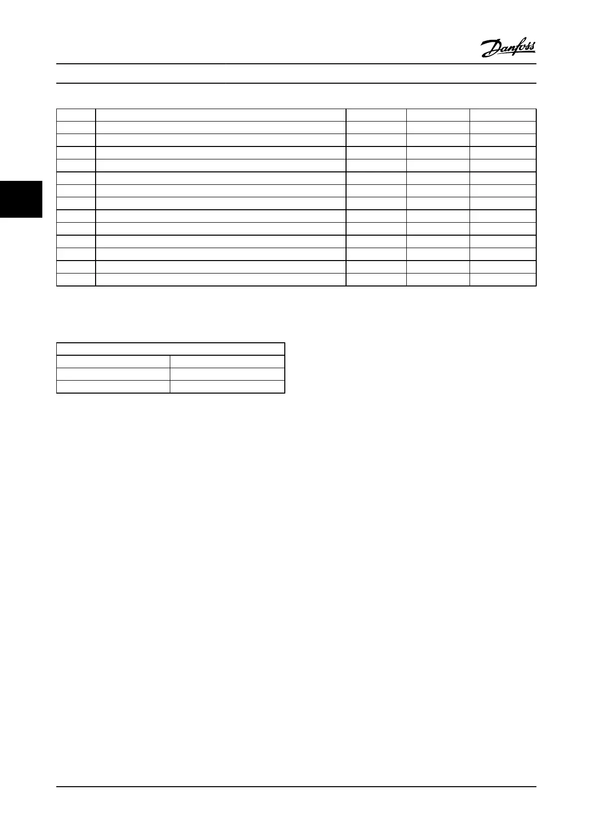
No. Description Warning Alarm/Trip Alarm/Trip Lock
309 Mains earth fault X
311 Switching frequency limit X
314 Auto CT interrupt X
315 Auto CT error X
316 CT location error X
317 CT polarity error X
318 CT ratio error X
319 Runaway follower X
320 AC resistor heatsink fault X
321 Voltage imbalance >3% X
322 5 V power card low X
323 15 V negative supply low X
324 15 V positive supply low X
Table 4.2 Warning/alarm code list
(X) Programmable: dependent on parameter setting.
1)
Cannot be auto reset via parameter selection.
LED indication
Warning yellow
Alarm flashing red
Trip locked yellow and red
Table 4.3
WARNING 1, 10 Volts low
The control card voltage is below 10 V from terminal 50.
Remove some of the load from terminal 50, as the 10 V
supply is overloaded. Max. 15 mA or minimum 590 Ω.
This condition can be caused by a short in a connected
potentiometer or improper wiring of the potentiometer.
Troubleshooting
Remove the wiring from terminal 50. If the warning clears,
the problem is with the customer wiring. If the warning
does not clear, replace the control card.
WARNING/ALARM 4, Mains phase loss
A phase is missing on the supply side, or the line voltage
imbalance is too high.
Troubleshooting: Check the supply voltage imbalance and
main fuses of the filter. Check the line cable connection for
tightness.
WARNING 5, DC link voltage high
The intermediate circuit voltage (DC) is higher than the
high voltage warning limit. The limit is dependent on the
filter voltage rating. The unit is still active.
See rating Table 1.4 in for the voltage limits.
WARNING 6, DC link voltage low
The intermediate circuit voltage (DC) is lower than the low
voltage warning limit. The limit is dependent on the filter
voltage rating. The unit is still active.
See rating
Table 1.4 in for the voltage limits.
WARNING/ALARM 7, DC overvoltage
If the intermediate DC link voltage exceeds the limit, the
filter trips after a time.
See rating Table 1.4 in for the voltage limits.
There are two different procedures for troubleshooting
alarm 7, depending upon the time the alarm occurs.
Alarm 7, DC overvoltage occurs immediately after starting
(run) the active filter:
•
Turn off the active filter
•
Measure the resistance to ground of the LCL
filter, AC capacitors, and damping resistors leads
with a megohmmeter to check for ground faults
•
Perform AC capacitors current transducers test
•
Check if the connectors on the current
transducers and on the AFC card are pinned
properly
•
Check AC capacitors current transducers cables
•
Replace the AFC card
Alarm 7, DC overvoltage occurs during the active filter
operation:
•
Perform the Line Power Resonance Test (6.3.7 Line
Power Resonance Test).
WARNING/ALARM 8, DC undervoltage
If the intermediate circuit voltage (DC link) drops below
the undervoltage limit, the filter checks if a 24 V backup
supply is connected. If no 24 V backup supply is
connected, the filter trips after a fixed time delay. The time
delay varies with unit size.
Troubleshooting VLT Advanced Active Filter AAF006 D and E Frames Service Manual
4-6 MG90Z122 - VLT
®
is a registered Danfoss trademark
44

 Loading...