Pin
No.
Sche
matic
Acron
ym
Function Description Reading Using a Digital
Voltmeter
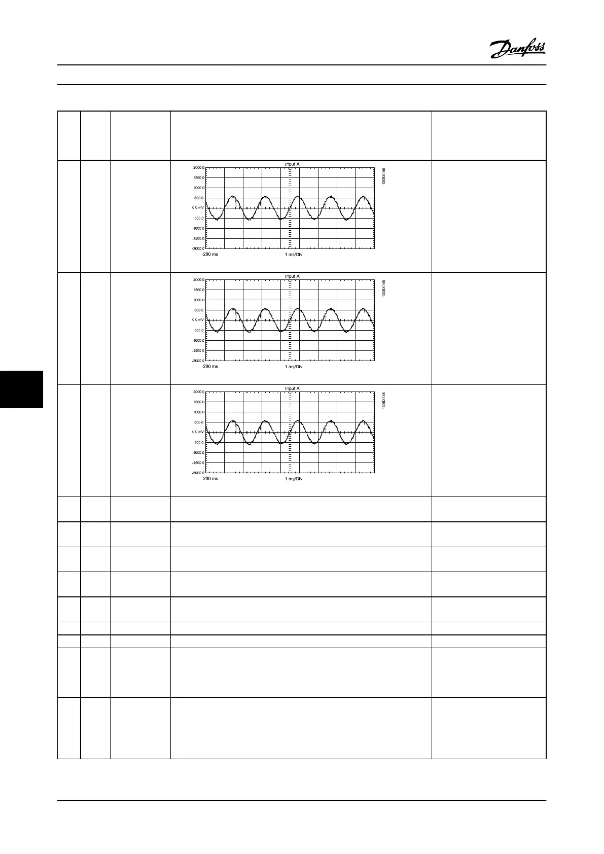
1 IU1 Current sensed,
U phase, not
conditioned
Approx 400 mV RMS @100% load
.937 V ACpeak @ 165% of CT
current rating. AC waveform @
output frequency of the filter.
2 IV1 Current sensed,
V phase, not
conditioned
Approx 400 mV RMS @100% load
.937 V ACpeak @ 165% of CT
current rating. AC waveform @
output frequency of the filter.
3 IW1 Current sensed,
W phase, not
conditioned
Approx 400 mV RMS @100% load
.937 V ACpeak @ 165% of CT
current rating. AC waveform @
output frequency of the filter.
4 COMM
ON
Logic common This common is for all signals.
5 AMBT Ambient temp. Used to control FAN high and low fan speeds. 1 V DC approximately equal to
25C
6 FANO Control Card
signal
Signal from the control card to turn the fans on and off. 0 V DC – ON command
5 V DC – OFF command
7 INRUS
H
Control Card
signal
Signal from the control card to start gating the SCR front end 3.3 V DC – SCRs disabled
0 V DC – SCRs enabled
8 RL1 Control Card
signal
Signal from Control Card to provide status of Relay 01 0 V DC – Relay active
0.7 V DC – inactive
9 Not used
10 Not used
11 VPOS +18 V DC
regulated
supply +16.5 to
19.5 V DC
The red LED indicates voltage is present between VPOS and VNEG
terminals.
+18 V DC regulated supply
+16.5 to 19.5 V DC
12 VNEG -18 V DC
regulated
supply
-16.5 to 19.5 V
DC
The red LED indicates voltage is present between VPOS and VNEG
terminals.
-18 V DC regulated supply
-16.5 to 19.5 V DC
Special Test Equipment VLT Advanced Active Filter AAF006 D and E Frames Service Manual
9-2 MG90Z122 - VLT
®
is a registered Danfoss trademark
99

 Loading...