Pin
No.
Sche
matic
Acron
ym
Function Description Reading Using a Digital
Voltmeter
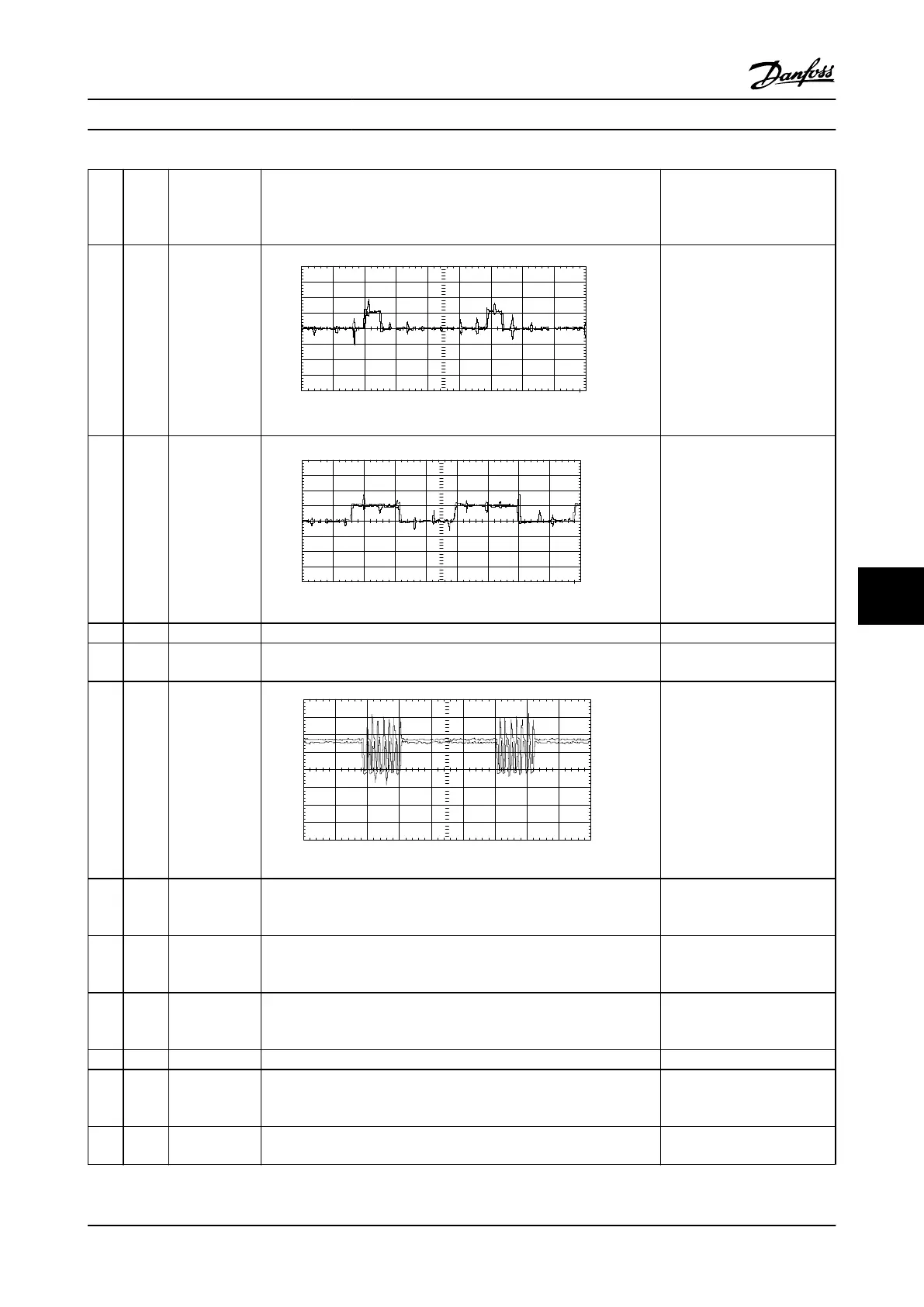
13 DBGAT
E
Brake IGBT gate
pulse train
20.0
15.0
10.0
5.0
0.0V
-5.0
-10.0
-15.0
-20.0
-400.0 us 20 us/Div.
Input A
130BX150.10
Varies w/ brake duty cycle
Voltage drops to zero when
brake is turned off. Voltage
increases to 4.04 V DC as
brake duty cycle reaches max.
14 BRT_O
N
Brake IGBT 5V
logic level
signal.
20.0
15.0
10.0
5.0
0.0V
-5.0
-10.0
-15.0
-20.0
-400.0 us 20 us/Div.
Input A
130BX151.10
Varies w/ brake duty cycle
5.10 V DC level with the brake
turned off. Voltage decreases
to zero as brake duty cycle
reaches max.
15 Not used
16 FAN_T
ST
Control signal
for fans
Indicates Fan Test switch is activated to force the fans on high +5V DC – disabled
0 V DC – fans on high
17 FAN_O
N
Pulse train to
gate SCR’s for
fan voltage
control. In sync
with line freq.
8.00
6.00
4.00
2.00
0.00 V
-2.00
-4.00
-6.00
-8.00
-4.0ms 2ms/Div
Input A
130BX152.10
7 trigger pulses at 3 kHz
5 V DC - fans off
18 HI_LO
W
Control signal
from Power
Card
Signal to switch fan speeds between high and low +5 V DC = fans on high,
Otherwise, 0 V DC.
19 SCR_DI
S
Control signal
for SCR front
end
Indicates SCR front end is enabled or disabled. 0.6 to 0.8 V DC – SCRs enabled
0 V DC – SCR disabled
20 INV_DI
S
Control signal
from Power
Card
Disables IGBT gate voltages 5 V DC – inverter disabled
0 V DC – inverter enabled
21 Not used
22 UINVE
X
Bus Voltage
scaled down
Signal proportional to UDC O V switch must be off
- 1 V DC = 450 V DC [T4/T5]
- 1 V DC = 610 V DC [T7]
23 VDD +24 V DC
power supply
Yellow LED indicates voltage is present. +24 V DC regulated supply
+23 to 25 V DC
Special Test Equipment VLT Advanced Active Filter AAF006 D and E Frames Service Manual
MG90Z122 - VLT
®
is a registered Danfoss trademark 9-3
9 9

 Loading...