Pin
No.
Sche
matic
Acron
ym
Function Description Reading Using a Digital
Voltmeter
24 VCC +5.0 V DC
regulated
supply. +4.75–
5.25 V DC
The green LED indicates voltage is present. +5.0 V DC regulated supply
+4.75–5.25 V DC
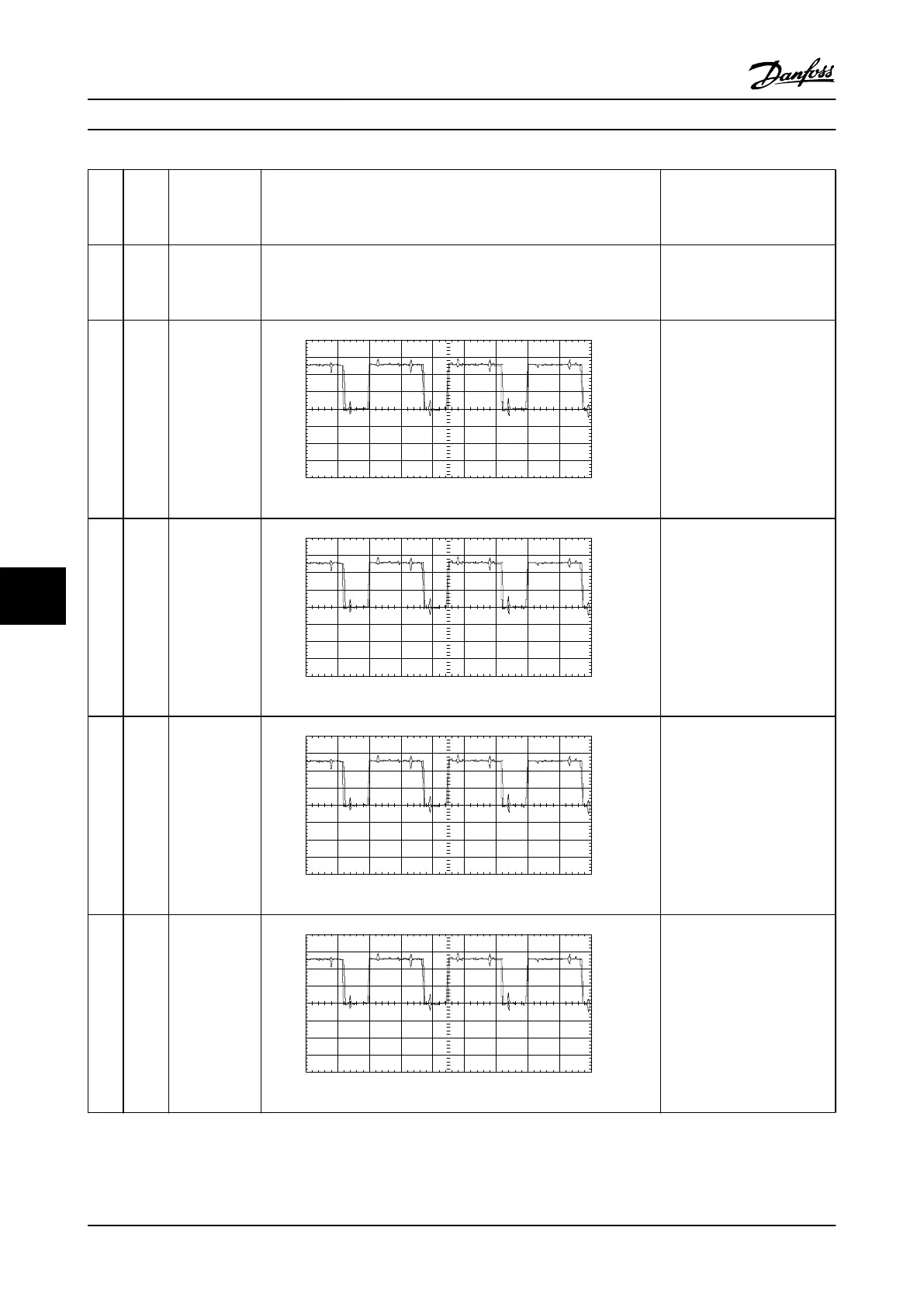
25 GUP_T IGBT gate
signal, buffered,
U phase,
positive. Signal
originates on
the control
card.
8.00
6.00
4.00
2.00
0.00 V
-2.00
-4.00
-6.00
-8.00
-4.0ms 50Us/Div
Input A
130BX153.10
2v/div 100us/div Run@10 Hz
2.2–2.5 V DC
Equal on all phases
TP25-TP30
26 GUN_T IGBT gate
signal, buffered,
U phase,
negative. Signal
originates on
the control
card.
8.00
6.00
4.00
2.00
0.00 V
-2.00
-4.00
-6.00
-8.00
-4.0ms 50Us/Div
Input A
130BX153.10
2v/div 100us/div Run@10 Hz
2.2–2.5 V DC
Equal on all phases
TP25-TP30
27 GVP_T IGBT gate
signal, buffered,
V phase,
positive. Signal
originates on
the control
card.
8.00
6.00
4.00
2.00
0.00 V
-2.00
-4.00
-6.00
-8.00
-4.0ms 50Us/Div
Input A
130BX153.10
2v/div 100us/div Run@10 Hz
2.2–2.5 V DC
Equal on all phases
TP25-TP30
28 GVN_T IGBT gate
signal, buffered,
V phase,
negative. Signal
originates on
the control
card.
8.00
6.00
4.00
2.00
0.00 V
-2.00
-4.00
-6.00
-8.00
-4.0ms 50Us/Div
Input A
130BX153.10
2v/div 100us/div Run@10 Hz
2.2–2.5 V DC
Equal on all phases
TP25-TP30
Special Test Equipment VLT Advanced Active Filter AAF006 D and E Frames Service Manual
9-4 MG90Z122 - VLT
®
is a registered Danfoss trademark
99

 Loading...