9.5 Cooling
NOTICE
Improper mounting can result in overheating and reduced performance. For proper mounting, refer to chapter 8 Exterior
and Terminal Dimensions.
•
Ensure that top and bottom clearance for air cooling is provided. Clearance requirement: 225 mm (9 in).
•
Provide sucient airow ow rate. See Table 9.2.
•
Consider derating for temperatures starting between 45 °C (113 °F) and 50 °C (122 °F) and elevation 1000 m (3300
ft) above sea level. See chapter 9.6 Derating for detailed information on derating.
The drive utilizes a back-channel cooling concept that removes heat sink cooling air. The heat sink cooling air carries
approximately 90% of the heat out of the back channel of the drive. Redirect the back-channel air from the panel or room
by using:
•
Duct cooling
Back-channel cooling kits are available to direct the heat sink cooling air out of the panel when IP20/Chassis drives
are installed in Rittal enclosures. Use of these kits reduce the heat in the panel and smaller door fans can be
specied.
•
Back-wall cooling
Installing top and base covers to the unit allows the back-channel cooling air to be ventilated out of the room.
NOTICE
A door fan is required on the enclosure to remove the heat losses not contained in the back channel of the drive and
those losses generated from other components installed inside the enclosure. The total required airow must be
calculated so that the appropriate fan is selected. Some enclosure manufacturers oer software for performing airow
calculations.
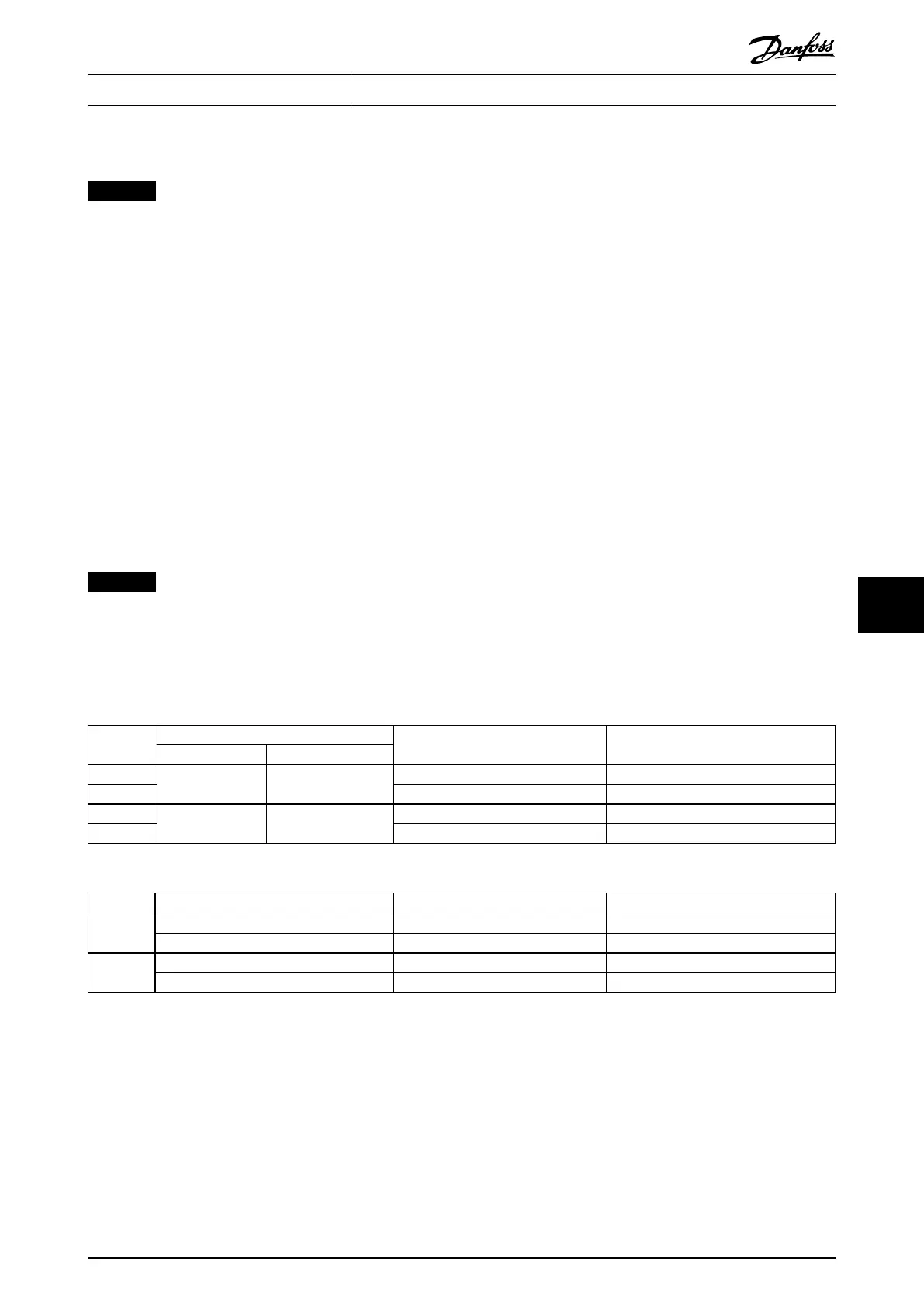
Secure the necessary airow over the heat sink.
Enclosure Models
Door fan/top fan [m
3
/hr (cfm)] Heat sink fan [m
3
/hr (cfm)]
380–480 V 525–690 V
E1 – P450–P500 340 (200) 1105 (650)
E2 255 (150) 1105 (650)
E1 P355–P450 P560–P630 340 (200) 1445 (850)
E2 255 (150) 1445 (850)
Table 9.2 E1–E2 Airow Rate
Enclosure Protection type
Door fan/top fan [m
3
/hr (cfm)] Heat sink fan [m
3
/hr (cfm)]
F1–F4 IP21/Type 1 700 (412) 985 (580)
IP54/Type 12 525 (309) 985 (580)
F8–F13 IP21/Type 1 700 (412) 985 (580)
IP54/Type 12 525 (309) 985 (580)
Table 9.3 F1–F4 and F8–F13 Airow Rates
Mechanical Installation Con... Design Guide
MG16C302 Danfoss A/S © 11/2017 All rights reserved. 161
9 9
 Loading...


