Using RCDs
Where residual current devices (RCDs), also known as
ground leakage circuit breakers, are used, comply with the
following:
•
Use RCDs of type B only as they can detect AC
and DC currents.
•
Use RCDs with a delay to prevent faults due to
transient ground currents.
•
Dimension RCDs according to the system congu-
ration and environmental considerations.
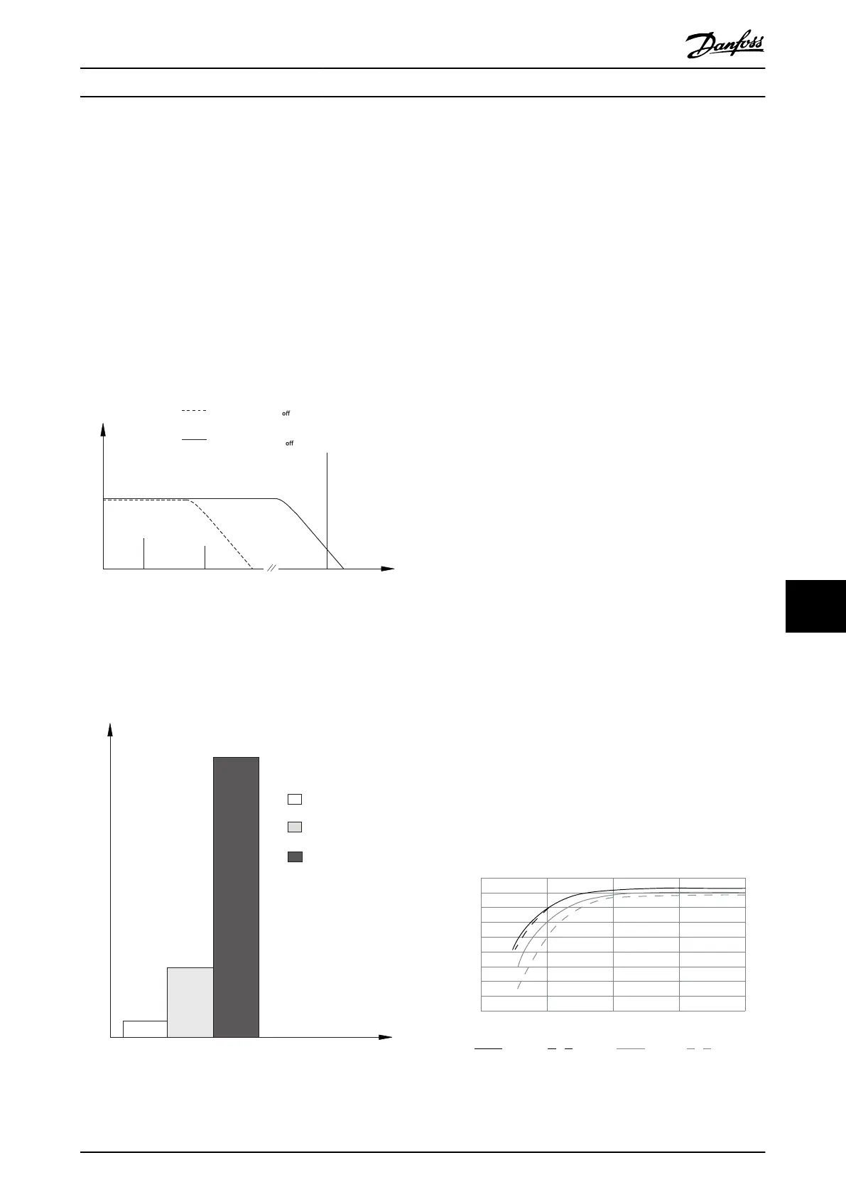
The leakage current includes several frequencies
originating from both the mains frequency and the
switching frequency. Whether the switching frequency is
detected depends on the type of RCD used.
130BB958.12
f
sw
Cable
150 Hz
3rd harmonics
50 Hz
Mains
RCD with low f
cut-
RCD with high f
cut-
Leakage current
Frequency
Illustration 10.23 Main Contributions to Leakage Current
The amount of leakage current detected by the RCD
depends on the cut-o frequency of the RCD.
130BB957.11
Leakage current [mA]
100 Hz
2 kHz
100 kHz
Illustration 10.24 Inuence of the RCD Cut-o Frequency on
Leakage Current
10.11
IT Grid
Mains supply isolated from ground
If the drive is supplied from an isolated mains source (IT
mains, oating delta, or grounded delta) or TT/TN-S mains
with grounded leg, the RFI switch is recommended to be
turned o via parameter 14-50 RFI Filter on the drive and
parameter 14-50 RFI Filter on the lter. For more detail, see
IEC 364-3. In the o position, the lter capacitors between
the chassis and the DC link are cut o to avoid damage to
the DC link and to reduce the ground capacity currents,
according to IEC 61800-3.
If optimum EMC performance is needed, or parallel motors
are connected, or the motor cable length is above 25 m
(82 ft), Danfoss recommends setting parameter 14-50 RFI
Filter to [ON]. Refer also to the Application Note, VLT on IT
Mains. It is important to use isolation monitors that are
rated for use together with power electronics (IEC
61557-8).
Danfoss does not recommend using an output contactor
for 525–690 V drives connected to an IT mains network.
10.12 Eciency
Eciency of the drive (η
VLT
)
The load on the drive has little eect on its eciency. In
general, the eciency is the same at the rated motor
frequency f
M,N
, whether the motor supplies 100% of the
rated shaft torque or only 75%, in case of part loads.
The eciency of the drive does not change even if other
U/f characteristics are selected. However, the U/f character-
istics inuence the eciency of the motor.
The eciency declines slightly when the switching
frequency is set to a value of above 5 kHz. The eciency is
slightly reduced when the mains voltage is 480 V, or if the
motor cable is longer than 30 m (98 ft).
Drive eciency calculation
Calculate the eciency of the drive at dierent speeds and
loads based on Illustration 10.25. The factor in this graph
must be multiplied by the specic eciency factor listed in
the specication tables in chapter 7.1 Electrical Data, 380–
480 V and chapter 7.2 Electrical Data, 525–690 V.
1.0
0.99
0.98
0.97
0.96
0.95
0.93
0.92
0% 50% 100% 200%
0.94
Relative Eciency
130BB252.11
1.01
150%
% Speed
100% load 75% load 50% load 25% load
Illustration 10.25 Typical
Eciency Curves
Electrical Installation Con... Design Guide
MG16C302 Danfoss A/S © 11/2017 All rights reserved. 189
10 10
 Loading...


