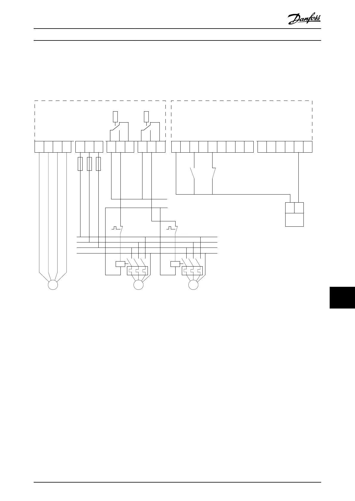
12.9 Wiring Conguration for Cascade Controller
Illustration 12.4 shows an example with the built-in basic cascade controller with 1 variable-speed pump (lead) and 2 xed-
speed pumps, a 4–20 mA transmitter, and system safety interlock.
Power Card
MOTOR MAINS
RELAY 1
(cascade
pump 1.)
RELAY 2
(cascade
pump 2.)
+24V OUT
+ 24V OUT
(Start)
(Safety Interlock)
(Feedback 1 res.)
Control Card
System
Start/
Stop
From Motor Control Circuitry
System
Safety
Interlock
Pressure
Transmitter
4-20 mA,
L1
L2
L3
PE
N
130BA378.10
P
24 V dc
12 13 18 19 27 29 32 33 20 39 42 50 53 54 55
COM D IN
D IN 1
D IN1
D IN1/D OUT
D IN1/D OUT
D IN 1
D IN 1
A IN2
A OUT1
COM A OUT
+ 10V OUT
A IN1
COM A IN
96
U
97
V
98
W
PE
91
L1
92
L2
93
L3
01 02 03 04 05 06
MMM
Illustration 12.4 Cascade Controller Wiring Diagram
Application Examples Design Guide
MG16C302 Danfoss A/S © 11/2017 All rights reserved. 213
12 12
 Loading...


