Shielding of cables
NOTICE
The motor cable must be shielded. If an unshielded cable
is used, some EMC requirements are not complied with.
Use a shielded motor cable to comply with EMC emission
specications. For more information, see
chapter 10.16 EMC-compliant Installation.
Avoid installation with twisted shield ends (pigtails). They
spoil the shielding eect at higher frequencies. If it is
necessary to break the shield, continue the shield at the
lowest possible HF impedance.
Connect the motor cable shield to both the decoupling
plate of the drive and the metal housing of the motor.
Make the shield connections with the largest possible
surface area (cable clamp) by using the installation devices
within the drive.
Cable length and cross-section
The drive has been EMC tested with a given length of
cable. Keep the motor cable as short as possible to reduce
the noise level and leakage currents.
Switching frequency
When drives are used together with sine-wave
lters to
reduce the acoustic noise from a motor, the switching
frequency must be set according to the instructions in
parameter 14-01 Switching Frequency.
Terminals Connection type
96 97 98 99
U V W
PE
1)
Motor voltage 0–100% of
mains voltage. 3 wires out of
motor.
U1 V1 W1
PE
1)
Delta-connected.
W2 U2 V2 6 wires out of motor.
U1 V1 W1
PE
1)
Star-connected U2, V2, W2.
U2, V2, and W2 to be intercon-
nected separately.
Table 10.1 Motor Cable Connections, Enclosures E1–E2 and
F1–F4
1) Protected ground connection
Terminals Connection type
96 97 98 99
U V W
PE
1)
Motor voltage 0–100% of
mains voltage.
3 wires out of motor.
U1 V1 W1
PE
1)
Delta-connected.
W2 U2 V2 6 wires out of motor.
U1 V1 W1
PE
1)
Star-connected U2, V2, W2.
U2, V2, and W2 to be intercon-
nected separately.
Table 10.2 Motor Cable Connections, Enclosures F8–F13
1) Protective ground connection
NOTICE
In motors without phase insulation, paper, or other
insulation reinforcement suitable for operation with
voltage supply, use a sine-wave lter on the output of
the drive.
U
1
V
1
W
1
175ZA114.11
96 97 98
96 97 98
FC
FC
Motor
Motor
U
2
V
2
W
2
U
1
V
1
W
1
U
2
V
2
W
2
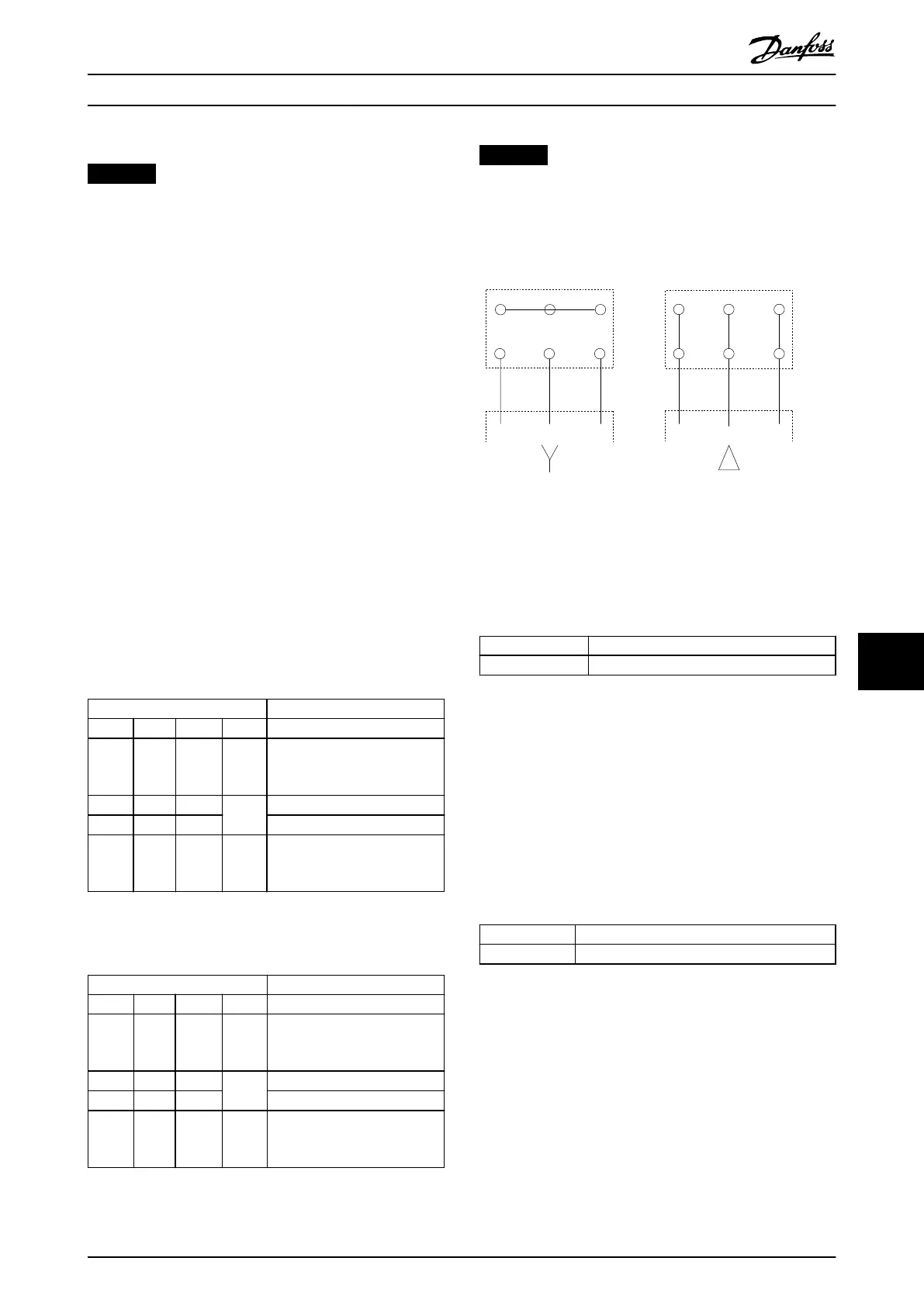
Illustration 10.5 Motor Cable Connection
10.3.2 DC Bus Connection
The DC bus terminal is used for DC back-up, with the DC
link being supplied from an external source.
Terminal Function
88, 89 DC Bus
Table 10.3 DC Bus Terminals
10.3.3 Load Sharing Connection
Load sharing links together the DC intermediate circuits of
several drives. For an overview, see chapter 5.6 Load Share
Overview.
The load sharing feature requires extra equipment and
safety considerations. Consult Danfoss for ordering and
installation recommendations.
Terminal Function
88, 89 Load sharing
Table 10.4 Load Sharing Terminals
The connection cable must be shielded and the maximum
length from the drive to the DC bar is limited to 25 m
(82 ft).
Electrical Installation Con... Design Guide
MG16C302 Danfoss A/S © 11/2017 All rights reserved. 169
10 10
 Loading...


