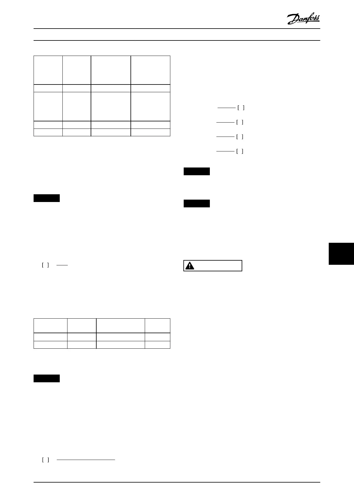
380–480 V
Model
Cycle time
(s)
Braking duty
cycle at 100%
torque
Braking duty
cycle at over
torque
(150/160%)
P355–P1000 600 40% 10%
525–690
Model
Cycle time
(s)
Braking duty
cycle at 100%
torque
Braking duty
cycle at over
torque
(150/160%)
P560–P630 600 40% 10%
P710–P1M4 600 40% 10%
Table 10.34 Braking at High Overload Torque Level
Danfoss oers brake resistors with duty cycle of 5%, 10%,
and 40%. If a 10% duty cycle is applied, the brake resistors
are able to absorb brake power for 10% of the cycle time.
The remaining 90% of the cycle time is used to dissipate
excess heat.
NOTICE
Make sure that the resistor is designed to handle the
required braking time.
The maximum allowed load on the brake resistor is stated
as a peak power at a given intermittent duty cycle. The
brake resistance is calculated as shown:
R
br
Ω =
U
dc
2
P
peak
where
P
peak
=P
motor
xM
br
[%]xη
motor
xη
VLT
[W]
As can be seen, the brake resistance depends on the DC-
link voltage (U
dc
).
Size Brake
active
Warning before
cutout
Cutout
(trip)
380–480 V
1)
810 V 828 V 855 V
525–690 V 1084 V 1109 V 1130 V
Table 10.35 FC 102/FC 202 Brake Limits
1) Power size dependent
NOTICE
Check that the brake resistor can handle a voltage of
410 V, 820 V, 850 V, 975 V, or 1130 V. Danfoss brake
resistors are rated for use on all Danfoss drives.
Danfoss recommends the brake resistance R
rec
. This
calculation guarantees that the drive is able to brake at the
highest brake power (M
br(%)
) of 150%. The formula can be
written as:
R
rec
Ω =
U
dc
2
x100
P
motor
xM
br( % )
xη
VLT
xη
motor
η
motor
is typically at 0.90
η
VLT
is typically at 0.98
For 200 V, 480 V, 500 V, and 600 V drives, R
rec
at 160%
brake power is written as:
200V:R
rec
=
107780
P
motor
Ω
500V:R
rec
=
464923
P
motor
Ω
600V:R
rec
=
630137
P
motor
Ω
690V:R
rec
=
832664
P
motor
Ω
NOTICE
The resistor brake circuit resistance selected should not
be higher than what Danfoss recommends.
NOTICE
If a short circuit occurs in the brake transistor, power
dissipation in the brake resistor is prevented only by
using a mains switch or contactor to disconnect the
mains from the drive, or a contact in the brake circuit.
Uninterrupted power dissipation in the brake resistor can
cause overheating, damage, or a re.
WARNING
FIRE HAZARD
Brake resistors get hot during and after braking. Failure
to place the brake resistor in a secure area can result in
property damage and/or serious injury.
•
Ensure that the brake resistor is placed in a
secure environment to avoid re risk.
•
Do not touch the brake resistor during or after
braking to avoid serious burns.
10.8.2 Control with Brake Function
A relay/digital output can be used to protect the brake
resistor against overloading or overheating by generating a
fault in the drive. If the brake IGBT is overloaded or
overheated, the relay/digital signal from the brake to the
drive turns o the brake IGBT. This relay/digital signal does
not protect against a short circuit in the brake IGBT or a
ground fault in the brake module or wiring. If a short
circuit occurs in the brake IGBT, Danfoss recommends a
means to disconnect the brake.
In addition, the brake makes it possible to read out the
momentary power and the average power for the latest
120 s. The brake can monitor the power energizing and
make sure that it does not exceed the limit selected in
Electrical Installation Con... Design Guide
MG16C302 Danfoss A/S © 11/2017 All rights reserved. 187
10 10
 Loading...


