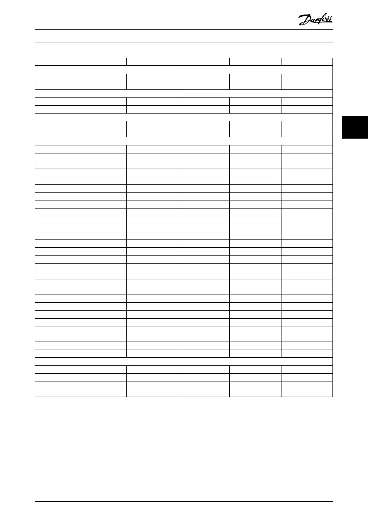
Enclosure size F1 F2 F3 F4
Power rating
1)
Output at 690 V (kW) 710–900 1000–1400 710–900 1000–1400
Output at 575 V (hp) 750–1050 1150–1550 750–1050 1150–1550
Front-end conguration
6-pulse S S S S
12-pulse – – – –
Protection rating
IP IP21/54 IP21/54 IP21/54 IP21/54
UL type Type 1/12 Type 1/12 Type 1/12 Type 1/12
Hardware options
2)
Stainless steel back channel O O O O
Mains shielding – – – –
Space heater and thermostat O O O O
Cabinet light with power outlet O O O O
RFI lter (Class A1) – – O O
NAMUR terminals – – – –
Insulation resistance monitor (IRM) – – O O
Residual current monitor (RCM) – – O O
Brake chopper (IGBTs) O O O O
Safe Torque O O O O O
Regen terminals O O O O
Common motor terminals O O O O
Emergency stop with Pilz safety relay – – O O
Safe Torque O with Pilz safety relay O O O O
No LCP – – – –
Graphical LCP S S S S
Numerical LCP – – – –
Fuses O O O O
Load share terminals O O O O
Fuses + load share terminals O O O O
Disconnect – – O O
Circuit breakers – – O O
Contactors – – O O
Manual motor starters O O O O
30 A, fuse-protected terminals O O O O
24 V DC supply (SMPS, 5 A) O O O O
External temperature monitoring O O O O
Dimensions
Height, mm (in) 2204 (86.8) 2204 (86.8) 2204 (86.8) 2204 (86.8)
Width, mm (in) 1400 (55.1) 1800 (70.9) 2000 (78.7) 2400 (94.5)
Depth, mm (in) 606 (23.9) 606 (23.9) 606 (23.9) 606 (23.9)
Weight, kg (lb) 1017 (2242.1) 1260 (2777.9) 1318 (2905.7) 1561 (3441.5)
Table 4.7 F1–F4 Drives, 525–690 V
1) All power ratings are taken at normal overload. Output is measured at 690 V (kW) and 575 V (hp).
2) S = standard, O = optional, and a dash indicates that the option is unavailable.
Product Overview Design Guide
MG16C302 Danfoss A/S © 11/2017 All rights reserved. 17
4 4
 Loading...


