5.2.3 Motor Thermal Protection
Motor thermal protection can be provided via:
•
Direct temperature sensing using a
- PTC- or KTY sensor in the motor
windings and connected on a standard
AI or DI.
- PT100 or PT1000 in the motor windings
and motor bearings, connected on VLT
®
Sensor Input Card MCB 114.
-
PTC Thermistor input on VLT
®
PTC
Thermistor Card MCB 112 (ATEX
approved).
•
Mechanical thermal switch (Klixon type) on a DI.
•
Built-in electronic thermal relay (ETR).
ETR calculates motor temperature by measuring current,
frequency, and operating time. The drive shows the
thermal load on the motor in percentage and can issue a
warning at a programmable overload setpoint.
Programmable options at the overload allow the drive to
stop the motor, reduce output, or ignore the condition.
Even at low speeds, the drive meets I2t Class 20 electronic
motor overload standards.
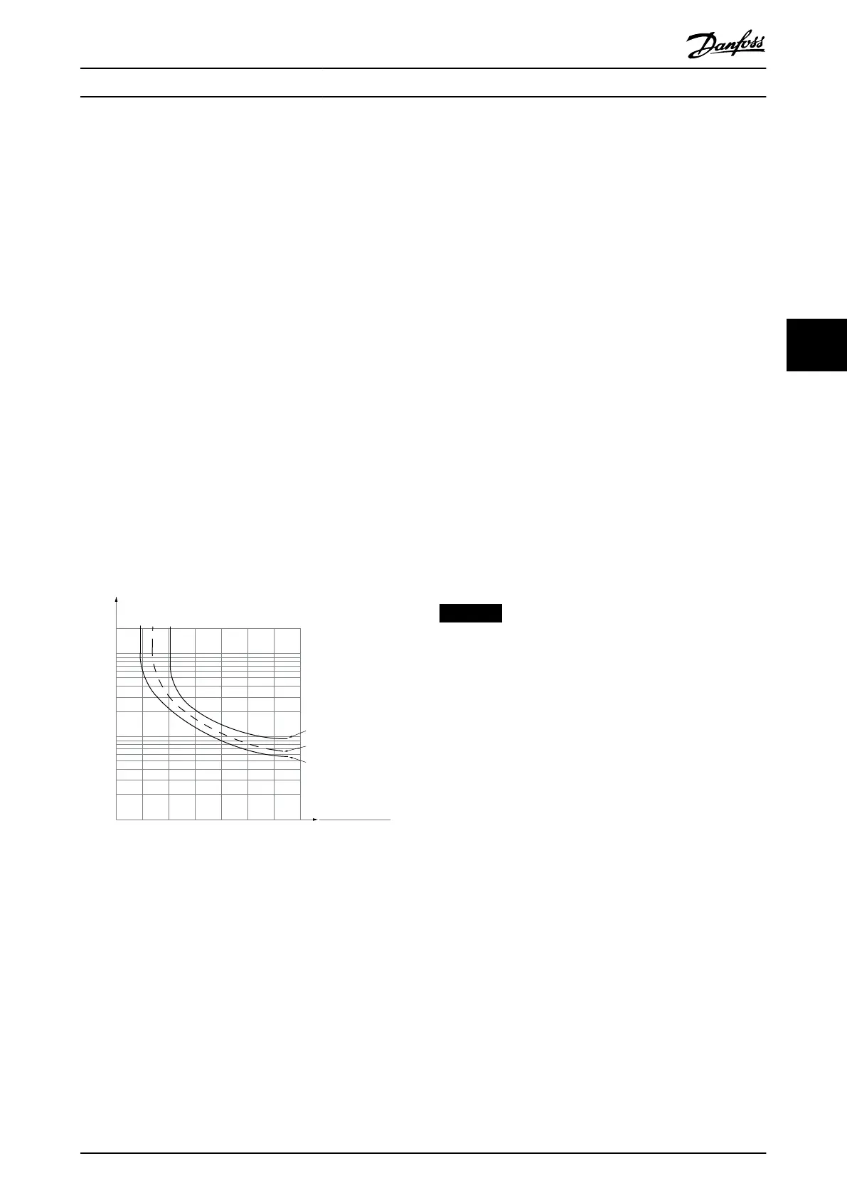
1.21.0 1.4
30
10
20
100
60
40
50
1.81.6 2.0
2000
500
200
400
300
1000
600
t [s]
175ZA052.12
f
OUT
= 2 x f
M,N
f
OUT
= 0.2 x f
M,N
f
OUT
= 1 x f
M,N
(par. 1-23)
I
MN
(par. 1-24)
I
M
Illustration 5.1 ETR Characteristics
The X-axis shows the ratio between I
motor
and I
motor
nominal. The Y-axis shows the time in seconds before the
ETR cuts o and trips the drive. The curves show the
characteristic nominal speed, at twice the nominal speed
and at 0.2 x the nominal speed.
At lower speed, the ETR cuts o at lower heat due to less
cooling of the motor. In that way, the motor is protected
from being overheated even at low speed. The ETR feature
calculates the motor temperature based on actual current
and speed. The calculated temperature is visible as a
readout parameter in parameter 16-18 Motor Thermal.
A special version of the ETR is also available for EX-e
motors in ATEX areas. This function makes it possible to
enter a specic curve to protect the Ex-e motor. See the
programming guide for set-up instructions.
5.2.4 Motor Thermal Protection for Ex-e
Motors
The drive is equipped with an ATEX ETR thermal
monitoring function for operation of Ex-e motors according
to EN-60079-7. When combined with an ATEX approved
PTC monitoring device such as the VLT
®
PTC Thermistor
Card MCB 112 or an external device, the installation does
not require an individual approval from an approbated
organization.
The ATEX ETR thermal monitoring function enables use of
an Ex-e motor instead of a more expensive, larger, and
heavier Ex-d motor. The function ensures that the drive
limits motor current to prevent overheating.
Requirements related to the Ex-e motor
•
Ensure that the Ex-e motor is approved for
operation in hazardous zones (ATEX zone 1/21,
ATEX zone 2/22) with drives. The motor must be
certied for the specic hazardous zone.
•
Install the Ex-e motor in zone 1/21 or 2/22 of the
hazardous zone, according to motor approval.
NOTICE
Install the drive outside the hazardous zone.
•
Ensure that the Ex-e motor is equipped with an
ATEX-approved motor overload protection device.
This device monitors the temperature in the
motor windings. If there is a critical temperature
level or a malfunction, the device switches o the
motor.
-
The VLT
®
PTC Thermistor MCB 112
option provides ATEX-approved
monitoring of motor temperature. It is a
prerequisite that the drive is equipped
with 3–6 PTC thermistors in series
according to DIN 44081 or 44082.
- Alternatively, an external ATEX-approved
PTC protection device can be used.
•
Sine-wave lter is required when the following
apply:
- Long cables (voltage peaks) or increased
mains voltage produce voltages
exceeding the maximum allowable
voltage at motor terminals.
- Minimum switching frequency of the
drive does not meet the requirement
stated by the motor manufacturer. The
minimum switching frequency of the
Product Features Design Guide
MG16C302 Danfoss A/S © 11/2017 All rights reserved. 23
5 5
 Loading...


