Normal overload 110% for 1 minute
Adjustable frequency drive
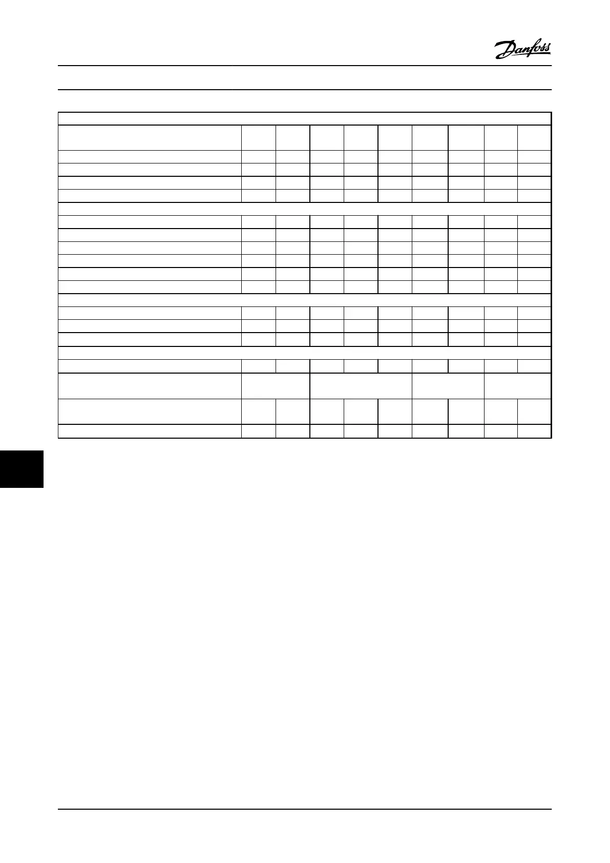
Typical Shaft Output [kW]
P15K
15
P18K
18.5
P22K
22
P30K
30
P37K
37
P45K
45
P55K
55
P75K
75
P90K
90
IP20/NEMA Chassis B3 B3 B4 B4 B4 C3 C3 C4 C4
IP21/NEMA 1 B1 B1 B2 B2 B2 C1 C1 C2 C2
IP55/NEMA 12 B1 B1 B2 B2 B2 C1 C1 C2 C2
IP66 B1 B1 B2 B2 B2 C1 C1 C2 C2
Output current
Continuous (3 x 525–550 V) [A] 23 28 36 43 54 65 87 105 137
Intermittent (3 x 525–550 V) [A] 25 31 40 47 59 72 96 116 151
Continuous (3 x 525–600 V) [A] 22 27 34 41 52 62 83 100 131
Intermittent (3 x 525–600 V) [A] 24 30 37 45 57 68 91 110 144
Continuous kVA (525 V AC) [kVA] 21.9 26.7 34.3 41 51.4 61.9 82.9 100 130.5
Continuous kVA (575 V AC) [kVA] 21.9 26.9 33.9 40.8 51.8 61.7 82.7 99.6 130.5
Max. input current
Continuous (3 x 525–600 V) [A] 20.9 25.4 32.7 39 49 59 78.9 95.3 124.3
Intermittent (3 x 525–600 V) [A] 23 28 36 43 54 65 87 105 137
Max. pre-fuses
1)
[A]
40 50 60 80 100 150 160 225 250
Additional specifications
Estimated power loss at rated max. load [W]
4)
285 329 460 560 740 860 890 1020 1130
Max. cable size (line power, motor, brake)
[mm
2
]/(AWG)
2)
[35]/(2) [50]/(1)
[95
5)
]/(3/0)
Weight enclosure IP20 (lb [kg]) 26.46
[12]
26.46
[12]
51.81
[23.5]
51.81
[23.5]
51.81
[23.5]
77.16
[35]
77.16
[35]
110.23
[50]
110.23
[50]
Efficiency
4)
0.98 0.98 0.98 0.98 0.98 0.98 0.98 0.98 0.98
Table 10.8 Line Power Supply 3 x 525–600 V AC
1)
For type of fuse, see 10.3.2 Fuse Tables
2)
American Wire Gauge
3)
Measured using 16 ft [5 m] shielded motor cables at rated load
and rated frequency
4)
The typical power loss is at normal load conditions and expected
to be within
±
15% (tolerance relates to variety in voltage and cable
conditions).
Values are based on a typical motor efficiency (eff2/eff3 border line).
Lower efficiency motors will also add to the power loss in the
adjustable frequency drive and vice versa.
If the switching frequency is raised from nominal, the power losses
may rise significantly.
LCP and typical control card power consumption values are included.
Further options and customer load may add up to 30 Watts to the
losses. (Though typically only 4 W extra for a fully loaded control
card or options for slot A or slot B, each).
Although measurements are made with state-of-the-art equipment,
some measurement inaccuracy must be allowed for (
±
5%).
5)
Motor and line cable: 300 MCM/150 mm
2
Specifications
VLT
®
AQUA Drive
Instruction Manual
10-8 MG20M922 - VLT
®
is a registered Danfoss trademark
10
10

 Loading...


