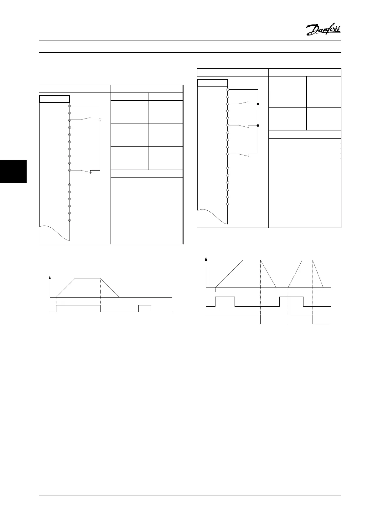
6.2.2 Start/Stop
Parameters
FC
+24 V
+24 V
D IN
D IN
D IN
COM
D IN
D IN
D IN
D IN
+10
A IN
A IN
COM
A OUT
COM
12
13
18
19
20
27
29
32
33
37
50
53
54
55
42
39
130BB802.10
Function Setting
Parameter 5-10
Terminal 18
Digital Input
[8] Start*
Parameter 5-12
Terminal 27
Digital Input
[0] No
operation
Parameter 5-19
Terminal 37
Digital Input
[1] Safe Stop
Alarm
* = Default Value
Notes/comments:
If parameter 5-12 Terminal 27
Digital Input is set to [0] No
operation, a jumper wire to
terminal 27 is not needed.
D IN 37 is an option.
Table 6.5 Start/Stop Command with Safe Stop Option
130BB805.11
Speed
Start (18)
Figure 6.2 Start/Stop Command with Safe Stop
Parameters
FC
+24 V
+24 V
D IN
D IN
D IN
COM
D IN
D IN
D IN
D IN
+10 V
A IN
A IN
COM
A OUT
COM
12
13
18
19
20
27
29
32
33
37
50
53
54
55
42
39
130BB803.10
Function Setting
Parameter 5-10
Terminal 18
Digital Input
[9] Latched
Start
Parameter 5-12
Terminal 27
Digital Input
[6] Stop
Inverse
* = Default Value
Notes/comments:
If parameter 5-12 Terminal 27
Digital Input is set to [0] No
operation, a jumper wire to
terminal 27 is not needed.
D IN 37 is an option.
Table 6.6 Pulse Start/Stop
Speed
130BB806.10
Latched Start (18)
Stop Inverse (27)
Figure 6.3 Latched Start/Stop Inverse
Application Examples
VLT
®
AQUA Drive FC 202 Low Harmonic Drive
62 Danfoss A/S © 10/2015 All rights reserved. MG21B322
6
6

 Loading...


