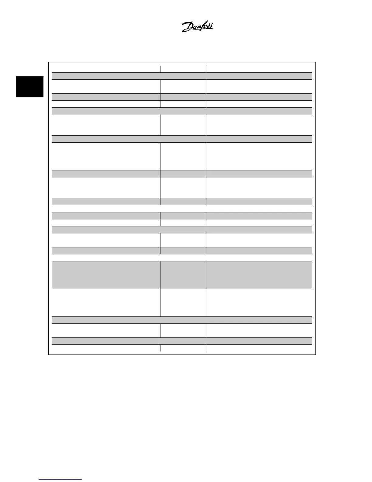
2.8.9 Programming Order
Function Par. no. Setting
1) Make sure the motor runs properly. Do the following:
Set the drive to control the motor based on drive output fre-
quency.
0-02
Hz
[1]
Set the motor parameters using nameplate data. 1-2* As specified by motor nameplate
Run Automatic Motor Adaptation. 1-29
Enable complete AMA
[1] and then run the AMA function.
2) Check that the motor is running in the right direction.
Press the “Hand On” LCP key and the ^ key to make the
motor turn slowly. Make sure that the motor runs in the cor-
rect direction.
If the motor runs in the wrong direction, remove power
temporarily and reverse two of the motor phases.
3) Make sure the adjustable frequency drive limits are set to safe values.
Make sure that the ramp settings are within the capabilities
of the drive and the allowed application operating specifica-
tions.
3-41
3-42
60 sec.
60 sec.
Depends on motor/load size!
Also active in hand mode.
Prohibit the motor from reversing (if necessary) 4-10
Clockwise
[0]
Set acceptable limits for the motor speed. 4-12
4-14
4-19
10 Hz,
Motor min speed
50 Hz,
Motor max speed
50 Hz,
Drive max output frequency
Switch from open-loop to closed-loop. 1-00
Closed-loop
[3]
4) Configure the feedback to the PID controller.
Set up Analog Input 54 as a feedback input. 20-00
Analog input 54
[2] (default)
Select the appropriate reference/feedback unit. 20-12
Bar
[71]
5) Configure the setpoint reference for the PID controller.
Set acceptable limits for the setpoint reference. 3-02
3-03
0 Bar
10 Bar
Set up Analog Input 53 as Reference 1 Source. 3-15
Analog input 53
[1] (default)
6) Scale the analog inputs used for setpoint reference and feedback.
Scale Analog Input 53 for the pressure range of the potenti-
ometer (0–10 Bar, 0–10 V).
6-10
6-11
6-14
6-15
0 V
10 V (default)
0 Bar
10 Bar
Scale Analog Input 54 for pressure sensor (0–10 Bar, 4–20
mA)
6-22
6-23
6-24
6-25
4 mA
20 mA (default)
0 Bar
10 Bar
7) Tune the PID controller parameters.
Adjust the drive’s closed-loop controller, if needed. 20-93
20-94
See Optimization of the PID Controller below.
8) Finished!
Save the parameter settings to the LCP for safekeeping. 0-50
All to LCP
[1]
2 Introduction to the VLT AQUA Drive VLT
®
AQUA Drive Design Guide
2-18
MG.20.N5.22 - VLT
®
is a registered Danfoss trademark
2
 Loading...


