EasyManuals Logo

Danfoss vlt aqua Design Guide

Danfoss vlt aqua
228 pages
To Next Page IconTo Next Page
To Previous Page IconTo Previous Page
Page #29 background imageLoading...
Page #29 background image
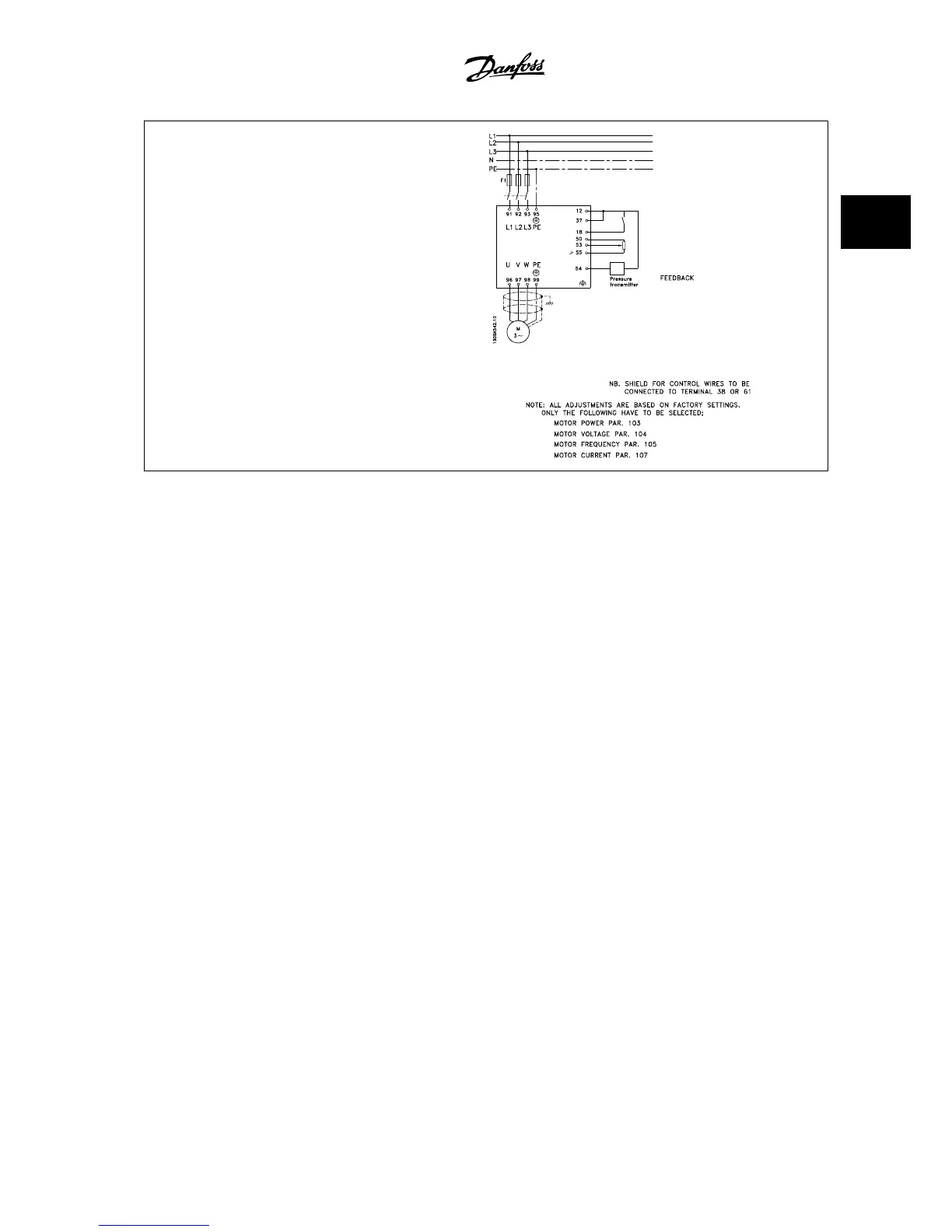
1. Start/Stop via switch connected between terminals 12 (+24 V) and 18.
2. Pressure reference via a potentiometer (0–10 Bar, 0–10 V) connected
to terminals 50 (+10 V), 53 (input) and 55 (common).
3. Pressure feedback via transmitter (0–10 Bar, 4–20 mA) connected to
terminal 54. Switch S202 behind the local control panel set to ON
(current input).
VLT
®
AQUA Drive Design Guide 2 Introduction to the VLT AQUA Drive
MG.20.N5.22 - VLT
®
is a registered Danfoss trademark
2-17
2

Table of Contents

Other manuals for Danfoss vlt aqua

Questions and Answers:

Question and Answer IconNeed help?

Do you have a question about the Danfoss vlt aqua and is the answer not in the manual?

Danfoss vlt aqua Specifications

General IconGeneral
Supply Voltage200-240V, 380-500V, 525-600V
EnclosureIP20
FeaturesEnergy optimization
ApprovalsCE, UL, cUL
Input Voltage Range200-240V, 380-500V, 525-600V
Output Voltage Range0 to supply voltage
Protection FeaturesOvervoltage, Undervoltage, Overcurrent, Short circuit, Ground fault
Communication InterfacesPROFIBUS
Cooling MethodAir-cooled

Related product manuals