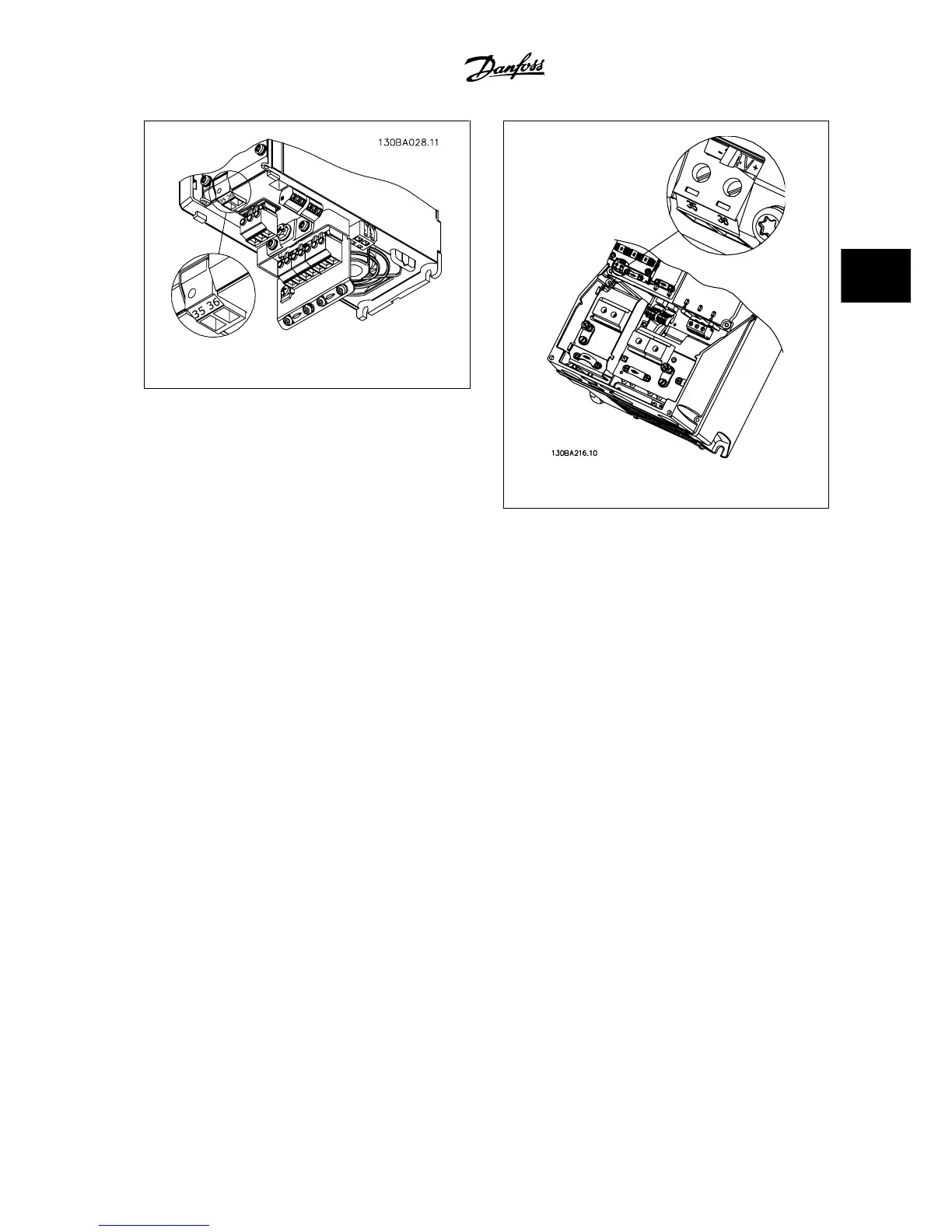
Figure 3.21: Connection to 24 V back-up supplier (A2-A3).
Figure 3.22: Connection to 24 V back-up supplier (A5-C2).
3.6.9 Analog I/O option MCB 109OPCAIO Analog I/O Option Module
The analog I/O card is supposed to be used in e.g., the following cases:
• Providing battery back-up of clock function on control card
• As general extension of analog I/O selection available on control card, e.g., for multi-zone control with three pressure transmitters
• Turning the adjustable frequency drive into a de-central I/O block supporting a Building Management System with inputs for sensors and outputs
for operating dampers and valve servos
• Support extended PID controllers with I/Os for setpoint inputs, transmitter/sensor inputs and outputs for switches.
VLT
®
AQUA Drive Design Guide 3 VLT AQUA Selection
MG.20.N5.22 - VLT
®
is a registered Danfoss trademark
3-37
3

 Loading...


