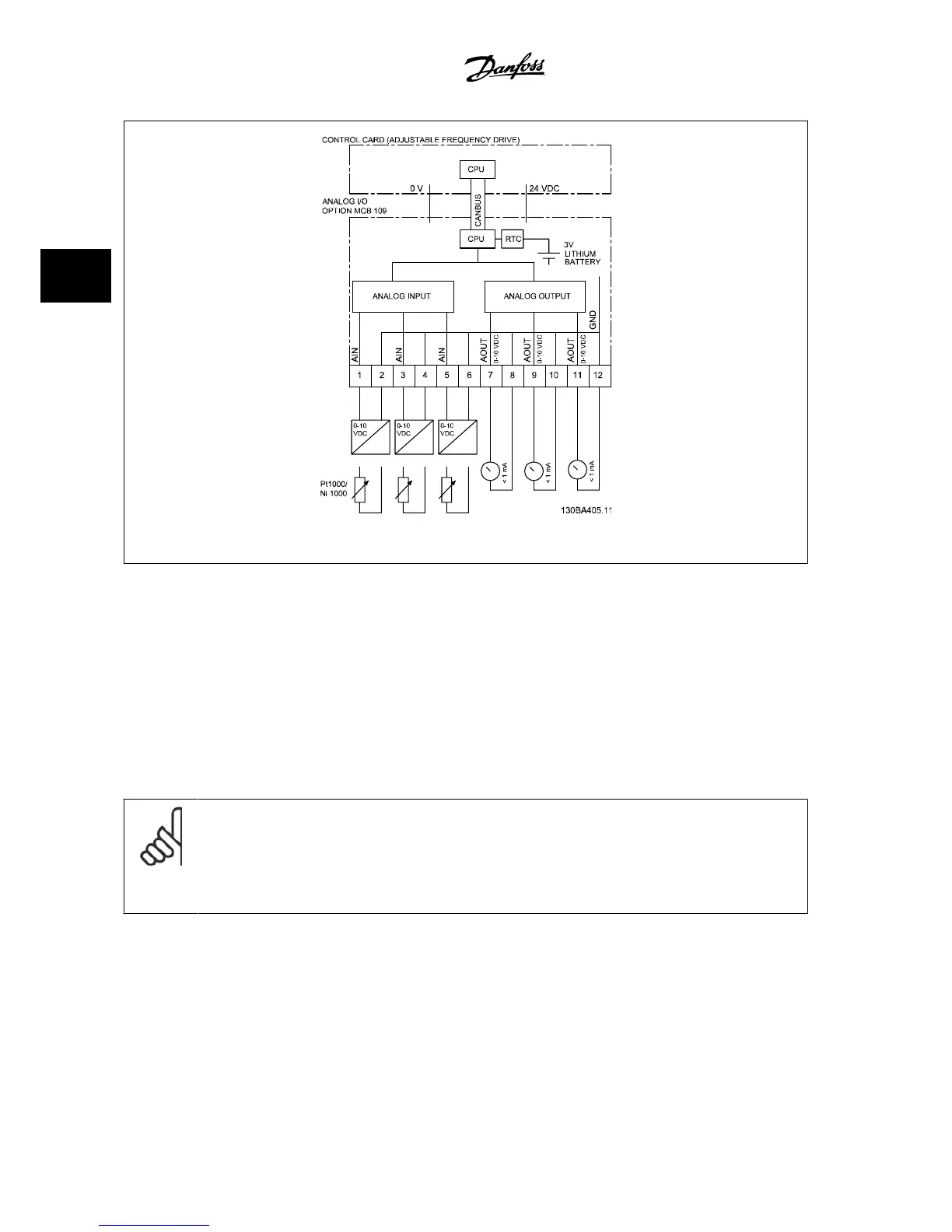
Figure 3.23: Principle diagram for analog I/O mounted in the adjustable frequency drive.
Analog I/O configuration
3 x analog inputs, capable of handling following:
• 0–10 VDC
OR
• 0–20 mA (voltage input 0–10 V) by mounting a 510Ω resistor across terminals (see NB!)
• 4–20 mA (voltage input 2–10 V) by mounting a 510Ω resistor across terminals (see NB)
•
Ni1000 temperature sensor of 1000 Ω at 0° C. Specifications according to DIN43760
• Pt1000 temperature sensor of 1000 Ω at 32°F [°C]. Specifications according to IEC 60751
3 x analog outputs supplying 0–10 V DC.
NOTE!
Please note the values available within the different standard groups of resistors:
E12: Closest standard value is 470Ω, creating an input of 449.9Ω and 8.997 V.
E24: Closest standard value is 510Ω, creating an input of 486.4Ω and 9.728 V.
E48: Closest standard value is 511Ω, creating an input of 487.3Ω and 9.746 V.
E96: Closest standard value is 523Ω, creating an input of 498.2Ω and 9.964 V.
Analog inputs - terminal X42/1-6
Parameter group for readout: 18-3*. See also
Programming Guide.
Parameter groups for set-up: 26-0*, 26-1*, 26-2* and 26-3*. See also
Programming Guide.
3 VLT AQUA Selection VLT
®
AQUA Drive Design Guide
3-38
MG.20.N5.22 - VLT
®
is a registered Danfoss trademark
3

 Loading...


