Each pump, variable speed or fixed-speed, is controlled by a relay in the master drive. The adjustable frequency drive with the cascade controller option
card installed has five relays available for controlling pumps. Two (2) relays are standard in the adjustable frequency drive and additional three relays
are found on the option card MCO 101 or 8 relays and 7 digital inputs on option card MCO 102.
The difference between the MCO 101 and the MCO 102 is mainly the number of optional relays available to the adjustable frequency drive. When the
MCO 102 is installed, the relays option card MCB 105 may be mounted in option slot B.
The cascade controller is capable of controlling a mix of variable speed and fixed-speed pumps. Possible configurations are described in more detail in
the next section. For simplicity of description within this manual, pressure and flow will be used to describe the variable output of the set of pumps
controlled by the cascade controller.
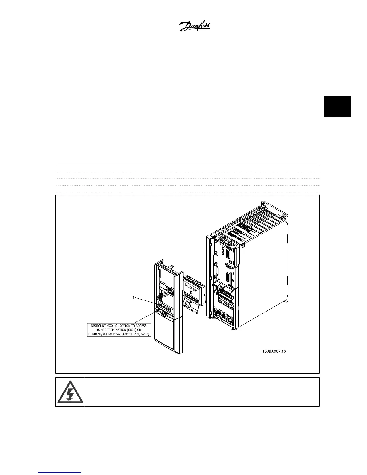
3.6.12 Extended Cascade Control MCO 101
The MCO 101 option includes three change-over contacts and can be inserted into option slot B.
Electrical Data:
Max terminal load (AC) 240 V AC 2A
Max terminal load (DC) 24 V DC 1 A
Min terminal load (DC) 5 V 10 mA
Max switching rate at rated load/min load 6 min
-1
/20 sec
-1
Figure 3.25: Mounting B-options
Warning Dual supply
VLT
®
AQUA Drive Design Guide 3 VLT AQUA Selection
MG.20.N5.22 - VLT
®
is a registered Danfoss trademark
3-41
3

 Loading...


