NOTE!
The label MUST be placed on the LCP frame as shown (UL-approved).
How to add the MCO 101 option:
• The power to the adjustable frequency drive must be disconnected.
• The power to the live part connections on relay terminals must be disconnected.
• Remove the LCP, the terminal cover and the cradle from the FC 202.
• Fit the MCO 101 option in slot B.
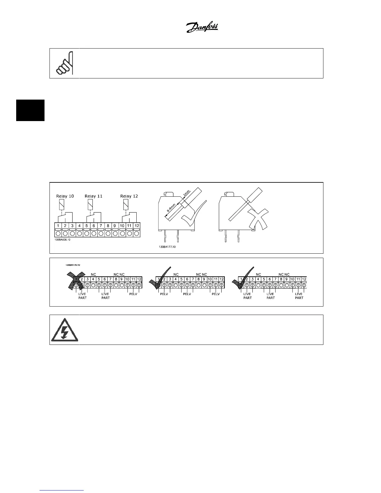
• Connect the control cables and fasten the cables by the enclosed cable strips.
• Different systems must not be mixed.
• Fit the extended cradle and terminal cover.
•Replace the LCP.
• Connect power to the adjustable frequency drive.
Wiring the Terminals
Do not combine low voltage parts and PELV systems.
3.6.13 Brake Resistors
In applications where the motor is used as a brake, energy is generated in the motor and sent back into the adjustable frequency drive. If the energy
cannot be transported back to the motor, it will increase the voltage in the drive DC line. In applications with frequent braking and/or high inertia loads,
this increase may lead to an overvoltage trip in the drive, and ultimately, a shut down. Brake resistors are used to dissipate the excess energy resulting
from the regenerative braking. The resistor is selected in respect to its ohmic value, its power dissipation rate and its physical size. Danfoss offers a wide
variety of different resistors that are specially designed to our adjustable frequency drives. See the section
Control with brake function
for the dimensioning
of brake resistors. Code numbers can be found in the section
How to order
.
3 VLT AQUA Selection VLT
®
AQUA Drive Design Guide
3-42
MG.20.N5.22 - VLT
®
is a registered Danfoss trademark
3

 Loading...


